Advertisement
Quick Links
Control Cover Kit
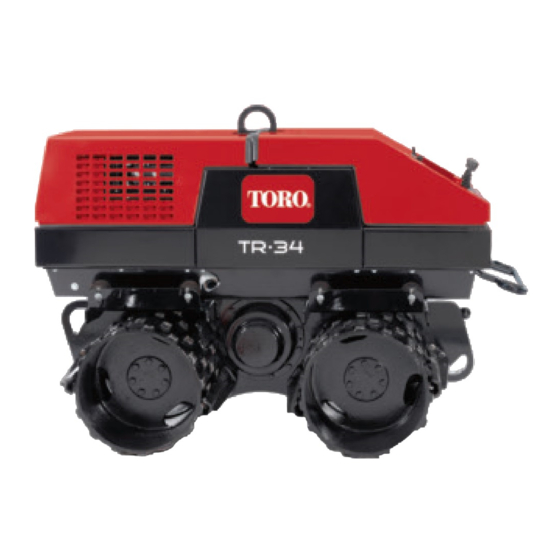
TR-34D Trench Roller
Model No. 68070
WARNING
CALIFORNIA
Proposition 65 Warning
This product contains a chemical or chemicals
known to the State of California to cause cancer,
birth defects, or reproductive harm.
Loose Parts
Use the chart below to verify that all parts have been shipped.
Description
No parts required
No parts required
Cover
Latch clip
Latch mount assembly
Catch mount assembly
Washer (5/16 inch)
Hex-socket bolt (1/4 x 5/8 inches)
Hex-socket bolt (1/4 x 1-1/4 inches)
Flange nut (1/4 inch)
Disconnecting the Battery
1. Open the rear hood; refer to the Opening the Hood
section in the Owner's Manual
2. Loosen the nut and bolt securing the negative-cable
clamp to the battery post, and remove the clamp from
the battery.
Note: Ensure that the negative-cable clamp does not
contact the battery post.
© 2013—The Toro® Company
8111 Lyndale Avenue South
Bloomington, MN 55420
Qty.
–
Disconnect the battery.
–
Drill the holes (machines without existing holes).
1
1
1
1
Install the control cover.
2
13
2
15
Drilling the Holes (Machines
without Existing Holes)
Register at www.Toro.com.
Installation Instructions
Use
1. Cover the rear compartment of the machine with
a drop cloth to protect the components in the
compartment from metal shavings that will be created
while drilling mounting holes for the control cover.
2. Align the cover left to right over the control panel
(Figure 1).
3. While keeping the hood centered, align the bottom
edge of the cover to the rear edge of the hood (Figure
1).
Original Instructions (EN)
All Rights Reserved *3377-640* B
Printed in the USA.
Form No. 3377-640 Rev B
Advertisement

Summary of Contents for Toro TR-34D
- Page 1 Form No. 3377-640 Rev B Control Cover Kit TR-34D Trench Roller Model No. 68070 Installation Instructions WARNING CALIFORNIA Proposition 65 Warning This product contains a chemical or chemicals known to the State of California to cause cancer, birth defects, or reproductive harm.
- Page 2 G021638 Figure 1 1. Rear edge of the hood 4. Cover 5. Holes in cover 2. Bottom edge of the cover 3. Hinged cover 6. Align the cover to the edge of the hood g021622 4. Using the cover as a template, mark the outline of the holes on the rear hood (Figure 2).
- Page 3 Installing the Control Cover 3. Assemble the latch clip to the latch mount with 2 hex-socket bolts (1/4 x 1-1/4 inches), 2 washers (5/16 1. Install the cover to the rear hood with 7 hex-socket inch), and 2 flange nuts (1/4 inch) (Figure 5). bolt (1/4 x 5/8 inches) and 7 flange nuts (1/4 inch) (Figure 3).


