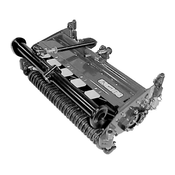
Summary of Contents for Toro REELMASTER 6000 Series
- Page 1 FORM NO. 3321-714 Rev A 80001 AND UP MODEL 03857— OPERATOR'S 80001 AND UP MODEL 03858— MANUAL 80001 AND UP MODEL 03859— ® 5, 7 & 11 BLADE REELS REELMASTER 6000 SERIES © The Toro Company 1998...
-
Page 2: Specifications
POWER: removal or installation onto the cutting unit. Cutting conventional single lip seals and a Toro labyrinth seal to units can be driven from either end. provide four sealing surfaces to protect the bearings. - Page 3 A 19-mm wrench will be needed to rotate the bedknife adjustment knob. Each notch on the knob Toro strongly recommends the use of a IMPORTANT: will move the bedknife .013 mm (Fig.2). leveling plate when setting up or adjusting any reel- type cutting unit.
- Page 4 larger gap between the reel blades and the bed ADJUSTING CUTTING UNIT knife exists on the left end than exists on the right ATTITUDE end (Fig. 4). Adjustable front and rear brackets allow infinite On the right end of the reel, insert a long strip of adjustment of cuffing unit “attitude”.
- Page 5 •• Front Roller Rear Support Hole Rear Cutting Unit Side Plate Hole •• Rear Thread Desired Height Thread of Cut Distance “R” Distance “F” Upper Lower *9.5 mm 13.5 mm 13.9 mm *12.7 mm 14.2 mm 9.1 mm 15.9 mm 17.5 mm 6.1 mm 19.0 mm...
- Page 6 FINAL HEIGHT-OF-CUT SETTING 5, 6 & CHART). Position the cutting unit on a flat level surface Using a gauge bar, Toro part no. 98-1852 or (leveling plate). equivalent (Fig. 9), set the head of the screw to the desired height of cut. This measurement is from the Position an 11.3mm or thicker bar under the reel...
- Page 7 Figure 10 Figure 11 1. Gauge bar 1. Shield fin 2. Grass shield 3. Capscrew IMPORTANT: Each reel must be set consistently. Minor differences in either height of cut or attitude ADJUST THE REAR SHIELD between cutting units may result in inconsistent quality of cut.
- Page 8 (2-SCREW GAUGE BAR) The cutting unit attitude may be adjusted or verified using a gauge bar, Toro part no. 98-1852, which has two screws and three hole locations. The second screw is used in the inner hole to set or verify cutting attitude.
- Page 9 Apply lapping compound with a long handle brush brake, and move the Enable/Disable switch to the (Toro Part No. 29-9100). Never use a short handled Disable position. brush. Unlock and raise the seat to expose the controls.
- Page 10 Lubrication GREASING BEARINGS, BUSHINGS AND PIVOT POINTS Each cutting unit has (6) grease fittings (Fig. 15) that must be lubricated regularly with No. 2 General Purpose Lithium Base Grease. Figure 15 The grease fitting locations shown in Figure 15 are for each side of the cutting unit.


