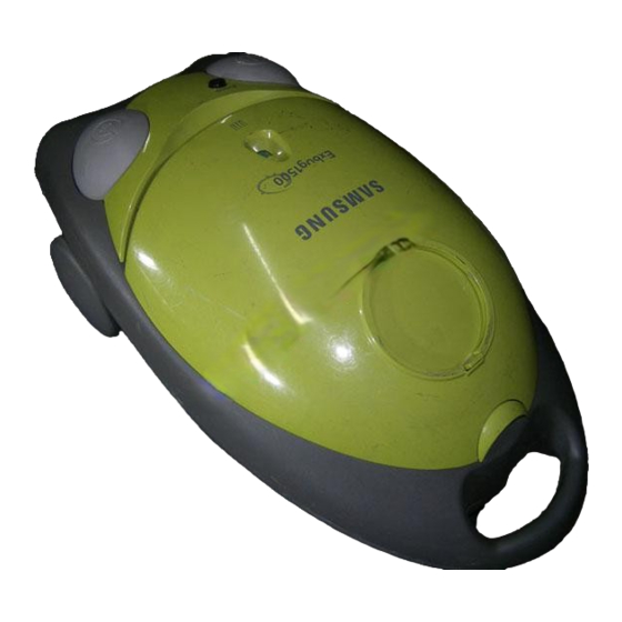
Summary of Contents for Samsung VC-7700 Series
-
Page 1: Table Of Contents
VACUUM CLEANER VC-7700 SERIES VACUUM CLEANER CONTENTS 1. Precautions 2. Specifications 3.Operating Instructions 4. Disassembly and Reassembly 5. Troubleshooting 6. Exploded Views and Parts List 7. Packing Diagram and Parts List 8. PCB Diagrams 9. Schematic Diagrams... - Page 2 Samsung Electronics Co., Ltd. APRIL. 1998. Printed in Korea. Code No. DJ68-40152A...
-
Page 3: Precautions
7. Grasp the plug firmly when removing it. To avoid damage to cord, plug, prongs or socket, always disconnect the cord from the electrical outlet before replacing the dust bag or servicing the cleaner. 8. The use of an extension cord is not recommended. 9. Repairs should be done only by an qualified serivce personnel. SAMSUNG ELECTRONICS., LTD... -
Page 4: Specifications
520mm(L) x 290mm(W) x 240mm(H) Dimension VC-7715H VC-7715V, 7714V Gross : 10 Kg Gross : 9.4Kg Weight : 6.1Kg : 6.1Kg (5.5) (5.5) excluding all accessories excluding all accessories Accessories Floor nozzle, Crevice tool, Dusting brush, Upholstery brush, Pipe, Hose. SAMSUNG ELECTRONICS., LTD... -
Page 5: Operating Instructions
3. Operating Instructions ACCESSORIES CREVICE TOOL DUSTING BRUSH UPHOLSTERY DUST BAG BRUSH SAMSUNG ELECTRONICS., LTD... -
Page 6: Disassembly And Reassembly
4. Disassembly and Reassembly 4-1 Removal of Panel & COVER-DUST ASS Y 1) Detach the Panel with a flat head screw driver. 2) Separate WIRE ASSÕY From the wafer on main body then detach COVER-DUST ASSÕY SAMSUNG ELECTRONICS., LTD... - Page 7 4-2 Disassembly of COVER-DUST ASS Y Loosen the four screws and detach INDICATOR ASSÕY, CAP-SLIDE and WIRE ASSÕY. 4-3 Removal of Main Body Release 11 screws and lift the main body upward. SAMSUNG ELECTRONICS., LTD...
-
Page 8: Motor Replacement
Seperate the WIRE ASSÕY from the MAIN-PCB ASSÕY and loosen the screw. 4-5 MOTOR replacement 1) Loosen the four screws and separate CASE-MOTOR,FRONT from the body. 2) Lossen the screw and separate MOTOR and ASSÕY CONNECTOR MOTOR. SAMSUNG ELECTRONICS., LTD... - Page 9 1) Detach the guard-cord with a flat head screw driver. 2) Separate the CORD-REEL from the body. 3) Hold the body reel and wind the power cord to the 5 times. 4) When the winding is completed, immediately assemble the CORD-REEL to the body. SAMSUNG ELECTRONICS., LTD...
-
Page 10: Troubleshooting
Remove the object indicator is in the red is not clogged with a large object position. Check that the spring of the dust Replace the spring indicator is ok Check that the filter sponge is clean Clean the sponge SAMSUNG ELECTRONICS., LTD... - Page 11 DJ67-50197B PIPE-CLAMPER ABS(S/GRY) DJ64-10193B KNOB-CLAMPER ABS(S/GRY) DJ72-10233B BODY-CLAMPER, L ABS(S/GRY) Location Code No. Description Specification Remarks DJ72-10234B ABS(S/GRY) BODY-CLAMPER, R DJ67-50146H PIPE-STEEL STEEL DJ61-20131B GUIDE-AIR PP(S/GRY) DJ67-50170B PIPE-T/STEEL TELESCOPIC : SNA (SERVICE NOT AVALILABLE) SAMSUNG ELECTRONICS., LTD SAMSUNG ELECTRONICS., LTD...
-
Page 12: Exploded Views And Parts List
ASSY M/GREEN DJ27-40106A COIL-HARMONIC DJ72-20132B PANEL-CONTROL ABS M/GREEN DJ64-10194A BUTTON-MITE ABS M/LIGHT DJ61-70192A SPRING-KNOB HSWR DJ73-20109A SEAL-DUST PVC M/GRY DJ63-40167A FILTER-GRILLE PP+HEPA DJ63-40170B FILTER-GRILLE 1T WHITE DJ41-20188B PBA-MAIN DJ31-30114D 220V DJ31-30114B MOTOR 230V DJ31-30114E 240V DJ27-40106A COIL-HARMONIC SAMSUNG ELECTRONICS CO., LTD. -
Page 13: Packing Diagram And Parts List
7. Packing Diagram and Parts List Location Code No. Description Specification Remarks DJ69-40170A PAD-UP DJ69-40174A PAD-BACK DJ69-60126A PACKING-PLUP PIPE-STEEL PACKING-CASE VACUUM CLEANER INSTRUCTION BOOK HOSE-ASSY DJ74-10124A BAG-PAPER ASSY 3PCS BRUSH-ASSY NB 200 SAMSUNG ELECTRONICS., LTD... -
Page 14: Pcb Diagrams
D J 3 9 - 2 0 2 5 8 B WIRE HARNESS W/HARNESS-C/DUST(7715V) D J 3 9 - 2 0 2 5 6 B DIAC 2 JUMPER-WIRE 3 8 1 2 - 0 0 0 2 1 9 SAMSUNG ELECTRONICS., LTD... -
Page 15: Schematic Diagrams
MODEL : VC-7715V, VC-7714V (BODY SLIDE V/R TYPE) COIL-HARMONIC MOTOR MAIN/SWITCH THERMOSTAT M/S(Harmonic-COIL switching) M/S 1(Body-CONTROL) 2(Mite-Hunter control) POWER SOURCE TRIAC 1 SLIDE SWITCH SEMI DIAC MODEL : VC-7715, 7714 (ON / OFF TYPE) MOTOR MAIN/SWITCH THERMOSTAT CIRCUIT-DIAGRAM POWER SOURCE SAMSUNG ELECTRONICS., LTD...


