Sign In
Upload
Manuals
Brands
Sony Manuals
VCR
RMT-DS11
Sony RMT-DS11 Remote Control Manuals
Manuals and User Guides for Sony RMT-DS11 Remote Control. We have
1
Sony RMT-DS11 Remote Control manual available for free PDF download: Service Manual
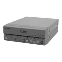
Sony RMT-DS11 Service Manual (172 pages)
DIGITAL VIDEO CASSETTE RECORDER
Brand:
Sony
| Category:
VCR
| Size: 31.87 MB
Table of Contents
Table of Contents
3
Service Note
5
Note for Repair
5
Self-Diagnosis Function
6
Self-Diagnosis Display
6
Service Mode Display
6
Self-Diagnosis Code Table
7
General
8
Features
8
Location and Function of Parts
8
Playback and Recording
10
Notes on Video Cassettes
10
Preparations
10
Playback
11
Recording
15
Installing the Unit Vertically
16
Operating the Menus
16
Troubleshooting
19
Alarm Messages
19
Notes on Use
19
Compatibility of DVCAM and DV Format
20
Disassembly
21
Upper Case
21
Front Panel Assembly
21
Board
21
DC/DC Converter Unit
21
Board
22
Mechanism Deck
22
Circuit Boards Location
23
Overall Block Diagram 1
24
Overall Block Diagram 2
25
Overall Block Diagram 3
26
Overall Block Diagram 4
27
Power Block Diagram 1
28
Power Block Diagram 2
29
Power Block Diagram 3
30
Power Block Diagram 4
31
Printed Wiring Boards and Schematic Diagrams
32
Frame Schematic Diagram (1/2)
33
Frame Schematic Diagram (2/2)
34
Printed Wiring Boards and Schematic Diagrams
35
Printed Wiring Board
35
VIDEO A/D CONVERTER) Schematic Diagram
42
AFC) Schematic Diagram
44
VFD (VIDEO DSP, D/A CONVERTER)) Schematic Diagram
45
SFD) Schematic Diagram
46
TFD) Schematic Diagram
47
DV INTERFACE) Schematic Diagram
48
MECHANISM CONTROL 1) Schematic Diagram
49
MECHANISM CONTROL 2) Schematic Diagram
50
MODE CONTROL) Schematic Diagram
51
AUDIO 1) Schematic Diagram
52
POWER SUPPLY) Schematic Diagram
54
Printed Wiring Board
55
INTERFACE) Schematic Diagram
57
VIDEO DECODER) Schematic Diagram
58
VIDEO OUTPUT) Schematic Diagram
59
AUDIO) Schematic Diagram
60
Y/C SEPARATION) Schematic Diagram
61
HI CONTROL) Schematic Diagram
62
MATRIX KEY CONTROL, LED DRIVE) Schematic Diagram
63
UVIC) Schematic Diagram
64
DC/DC CONVERTER, CAPSTAN MOTOR DRIVE, CAM MOTOR DRIVE) Schematic Diagram
65
DRUM MOTOR DRIVE, FL MOTOR DRIVE, REEL MOTOR DRIVE) Schematic Diagram
66
Printed Wiring Board
67
Printed Wiring Board
69
Schematic Diagram
70
Printed Wiring Board
71
Printed Wiring Board
73
Schematic Diagram
74
DC-1492 Printed Wiring Board
77
Waveforms
79
Parts Location
81
Adjustments
83
Before Starting Adjustment
83
Adjusting Items When Replacing Main Parts and Boards
84
Information (Mechanical Section)
86
Mechanical Section Adjustments
87
Parts Replacement and Preparation for Adjustment
87
Assembly/Disassembly of Cassette Compartment
87
How to Load/Unload
87
List of Service Tools
88
About Mode Selector II
89
Periodic Check
90
Cleaning of Rotary Drum Assembly
90
Cleaning of Tape Path System
90
Periodic Checks
90
Parts Replacement
91
Tape Guide 1/8 and Guide Guard
91
Tape Guide 2/7
91
Capstan Cover
92
Reel Motor
92
FL Motor Assembly, Gear A, Gear B and Gear CD Assembly
92
GL Arm S Assembly, GL Arm T Assembly, Coaster S Assembly and Coaster T Assembly
93
MIC Base Guide, MIC Base Assembly and MIC Base Spring
94
Drum Cap, Drum Assembly and Tape Support
94
Pinch Arm Assembly
95
Capstan Motor
95
Pendulum Retainer and Pendulum Arm Assembly
95
Brake Arm S, Ratchet Brake T
96
Flexible Board (Condensation Sensor)
96
Reel Table Assembly, Idler Gear a Assembly and Idler Gear B
96
Reel Base Retainer, Reel Base T Assembly and Reel Base S Assembly (Reel Lock Release Block and Reel Lock Release Spring)
97
Cam Motor, Motor Holder
97
TG2/7 Arm Block, TG2/7 Band Block and Tension Coil Spring (TG2)/(TG7)
98
Sub-Slider Arm, Sub-Slider, Encoder Gear, Main Cam Gear, Coupling Gear, Sub-Cam Gear, Pinch Slider and Loading Arm Assembly
99
Main Slider, Main Slider Arm and Pendulum Stopper Assembly
101
Board and Encoder Retainer
102
Components of GL Arm S/T Assembly (GL Arm Assembly, GL Helical Torsion Spring, GL Gear)
103
Components of MIC Base Assembly (FP-104 Flexible Board, MIC Base)
103
Components of Drum Assembly (Motor FPC Assembly, Elastic Connector)
104
Components of Pinch Arm Assembly (Tape Retainer, Compression Coil Spring)
104
Components of TG2/7 Arm Assembly (ET Magnet, Magnet Holder)
104
Check and Adjustment
105
Reel Table Height Check and Adjustment
106
TG1/8 Height Check and Adjustment
106
TG2/7 Height Check and Adjustment
107
FWD/RVS Position Check and Adjustment
107
Electric Tension Regulator Check and Adjustment of TG2/7 Arm
108
FWD/RVS Back Tension Check and Adjustment
109
Preparation for Adjustment and Tape Path Check
110
Track Adjustment and Check (Checking the RF Waveform)
111
Track Check
111
CUE/REV Check
112
Curl Check and Adjustment
112
Rising Check
113
Service Mode
114
Adjusting Remote Commander
114
Used Adjustment Remote Commander
114
Precautions Upon Using the Adjusting Remote Commander
114
Data Processing
115
Service Mode
116
Setting the Test Mode
116
Emergence Memory Address
116
EMG Code (Emergency Code)
117
MSW Code
117
Record of Use Check
119
Video Section Adjustments
120
Preparations before Adjustment
120
Equipment Used
120
Connection of Equipment
121
Checking the Input Signals
122
S VIDEO Input
122
VIDEO Input
122
Adjustment Tapes
123
Input/Output Level and Impedance
124
System Control System Adjustments
125
Initializing the C, D, E
125
Input of C Page Initial Data
125
Input of D Page Initial Data
125
Input of E Page Initial Data
125
Modification of C, D, E
125
C Page Table
126
D Page Table
127
Node Unique ID No. Input
128
Servo and RF System Adjustments
130
Capstan FG Adjustment (HD-024 Board)
130
PLL F Pre-Adjustment (RP-234 Board)
130
Switching Position Adjustment (HD-024 Board)
130
RF-AGC Adjustment (RP-234 Board)
130
CLK DELAY and AEQ Adjustment (RP-234 Board)
131
PLL F Final Adjustment (RP-234 Board)
131
Video System Adjustments
131
Board Adjustment
131
VFD SPCK Adjustment (JC-20 Board)
131
A/D Converter Reference Voltage Adjustment (1) (JC-20 Board)
131
A/D Converter Reference Voltage Adjustment (2) (JC-20 Board)
131
Y Signal Clamp Reference Voltage Adjustment (JC-20 Board)
132
CR Signal Clamp Reference Voltage Adjustment (JC-20 Board)
132
CB Signal Clamp Reference Voltage Adjustment (JC-20 Board)
132
AFC Preliminary Adjustment (JC-20 Board)
132
AFC Picture Frame Adjustment (JC-20 Board)
132
AFC Adjustment (JC-20 Board)
132
Playback y Level Adjustment (JC-20 Board)
133
Playback C Level Adjustment (JC-20 Board)
133
Board Adjustment
134
Decoder Free Run Adjustment (NTSC) (VD-031Board)
134
Decoder Free Run Adjustment (PAL) (VD-031Board)
134
Y/C Separation Adjustment (VD-031 Board)
134
Recording Signal Level Adjustment (VD-031 Board)
136
General Adjustment
138
HUE Adjustment (NTSC)
138
HUE Adjustment (PAL)
138
AUDIO System Adjustments
139
Playing Level Check
139
E-E S/N Check
139
E-E Distortion Check
140
Arrangement Diagram for Adjustment Parts
141
Repair Parts List
142
Overall Assembly
142
Chassis Assembly-1
143
Chassis Assembly-2
144
Mechanism Deck Assembly (Drum Assembly)
145
Mechanism Deck Assembly (Gear, Arm)
146
Mechanism Deck Assembly (Motor, MD Board)
147
Mechanism Deck Assembly (Cassette Compartment)
148
Electrical Parts List
149
Hardware List
170
Accessories & Packing Materials
171
Advertisement
Advertisement
Related Products
Sony RMT-DS5
Sony RMT-D240A
Sony RMT-DS7
Sony RMT-V223A
Sony RMT-V307
Sony RMT-V243
Sony RMT-V288C
Sony RMT-V259N
Sony RMT-V203A
Sony RMT-V248
Sony Categories
Laptop
TV
CD Player
Camcorder
Digital Camera
More Sony Manuals
Login
Sign In
OR
Sign in with Facebook
Sign in with Google
Upload manual
Upload from disk
Upload from URL