Sign In
Upload
Manuals
Brands
Sony Manuals
Tape Deck
GY-8240FC
Sony GY-8240FC Manuals
Manuals and User Guides for Sony GY-8240FC. We have
2
Sony GY-8240FC manuals available for free PDF download: Maintenance Manual, Operation Manual
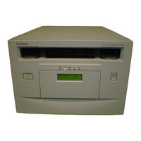
Sony GY-8240FC Maintenance Manual (444 pages)
DTF TAPE DRIVE
Brand:
Sony
| Category:
Tape Deck
| Size: 13.98 MB
Table of Contents
Table of Contents
3
Manual Structure
9
Purpose of this Manual
9
Relative Manual
9
Trademarks
10
Contents
9
1 Service Overview
11
Removal/Installation of Cabinet
11
Cassette Compartment Removal/Installation
12
Main Parts Layout
14
Main Mechanical Parts Layout
14
Printed Circuit Boards Layouts
15
Function Descriptions and Sensors Layouts
17
Internal Switch Setting
19
Connector/Cable Information
20
Taking out the Cassette in Tape Slacking
24
Fixtures and Measuring Equipment for Adjustment
25
Fixtures
25
Measuring Equipment
26
Alignment Tapes
27
Power Block
28
Switching Regulator Replacement
28
Fan Motor (Power Supply) Replacement
29
Voltage and Power Requirements
29
Power Cord
30
Replacement of the Boards
31
Index
31
And FM-75 Boards Replacement
32
And SCS-28, FC-82 Boards Replacement
32
Board Replacement
33
Board Replacement
34
Board Replacement
35
Functions of LED Indicators on Circuit Boards
37
Line Mode
38
Overview
38
Starting/Ending the Line Mode
39
Switch Function
40
Setting Mode
41
SCSI Control Software Scsitool.exe
43
Operating Environment
43
Connection
43
Starting
44
Ending
44
Functions
45
SCSITOOL-AGING Command
57
General Function Check Using the SCSI Control Function
63
Revision Label
67
Revision Label for Firmware/Hardware
67
Revision Label for Board
68
Update of the Firmware
69
Update with the Serial Port
69
Update with DTF-2 Cassette
71
Update with the Network (Ftp)
72
Update Using PSC
73
General Information of Device Connection
75
2 Periodic Maintenance and Inspection
77
Periodic Check
77
Hours Meter
77
Periodic Check List
78
Cleaning
80
General Information for Cleaning
80
Tape Running Surface of Upper Drum and Rotary Heads Cleaning
81
Tape Running Surface of Lower Drum and Lead Surface Cleaning
82
Stationary Heads Cleaning
83
Tape Running System and Tape Cleaner Cleaning
84
Cassette Compartment and Cassette Supports Cleaning
85
3 Replacement of Mechanical Parts
87
General Information for Parts Replacement
87
Notes
87
Index
88
Threading End Mode and Unthreading End Mode
90
L Cassette Position and S Cassette Position
92
Upper Drum Assembly Replacement
94
Drum Assembly Replacement
100
Brush Slip Ring Assembly Replacement
106
W Cleaner Assembly Cleaning Roller Replacement
109
CTL/TC Head Cleaner Replacement
113
CONFI Head Assembly Replacement
116
CTL/TC Head Replacement
118
Pinch Roller Replacement
122
Pinch Press Assembly Replacement
125
Capstan Motor Replacement
127
Reel Table Assembly Replacement and Adjustment
130
Reel Table Assembly Replacement
130
Reel Table Height Adjustment
132
Reel Brake Clearance Check
134
Reel Brake Release Amount Confirmation
135
Brake Lining Replacement
137
Reel Motor Plate Assembly Replacement
138
Reel Shift Motor Replacement
144
Reel Shift Gear Replacement
146
Tape Guide Replacement
148
Tape Cleaner Replacement
149
Gear Box Assembly Replacement
150
Threading Ring Assembly Replacement
153
S Tension Regulator Assembly Replacement
159
T Tension Regulator Assembly Replacement
161
T Drawer Assembly Replacement and Adjustment
164
T Drawer Assembly Replacement
164
Slant Guide Slantness Adjustment
171
Cassette Compartment Motor Replacement
175
Fan Motor Rear Panel Replacement
179
4 Tape Path Alignment
181
Genaral Information for Tape Path Adjustment
181
Notes
181
Preparation
182
Parts Location of the Tape-Running System
182
Locking Compound
183
CTL/TC Head Zenith Adjustment
184
Tape Running Adjustment
186
Tracking Adjustment
192
CTL/TC Head Height Adjustment
199
CTL/TC Head Azimuth Adjustment
202
CTL/TC Head Position Adjustment
205
Time Code Level Adjustment in Rev Mode
208
CONFI Head Height Adjustment
211
Drum Head Height Check
214
5 Maintenance Mode
217
Outline
217
Equipments Required and Connection
218
List of Menu Configurations
220
Activating the Maintenance Mode
220
Command Description
222
CUSTOM Mode
224
Quit Tool
224
Display Help Menu
224
Vendor Information Set
225
Vendor Information Display
226
Serial Number Set
226
Serial Number Display
227
DIAG Mode
228
Quit Tool
228
Display Help Menu
228
All Check
229
Dip Switch Display
229
ROM Version Display
230
Serial Number Display
230
Hours Meter Display
231
Hours Meter Clear
232
Maintenance Value Display
232
Maintenance Value Set
233
Fmt Cpu
233
Sys Cpu
235
Sv Cpu
237
If Cpu
262
Dsp Cpu
266
UPDATE Mode
272
Quit Tool
272
Display Help Menu
272
Help2
273
From Maintenance Port
274
From Tape
275
Sv Cpu
276
If Cpu
277
Dsp Cpu
278
LOG Mode
279
Quit Tool
279
Display Help Menu
279
Clear All Logs
279
Upload All Logs
279
Upload All Set Value and Logs
280
Fmt Cpu
280
Sys Cpu
286
SV CPU LOG Mode
313
If-Cpu
315
ROM Command
322
SERVICE Mode
323
Quit Tool
323
Display Help Menu
323
Service Information Set
324
Service Information Display
326
Default Service Information Set
327
ADJ Mode
328
Quit Tool
329
Display Help Menu
329
Help 2
330
SV Check
330
All Motors, Tension Sensors Adj
331
Auto
332
ATF Check
333
SAT Check
334
ADJ Mode Error Message
335
SETUP Mode
336
Quit Tool
336
Display Help Menu
336
Setup Information Set
337
Setup Information Display
341
Default Setup Information Set
342
THRU Mode
344
Quit Tool
344
Fmt Cpu
344
Sys Cpu
345
Sv Cpu
345
DEF Mode
346
Quit Tool
346
Display Help Menu
346
Gy-Uwd
347
Gy-Fc
349
Troubleshooting
351
Outline
351
Acquiring Logs
355
Using the Self-Diagnosis Mode
357
LCD Display and Unit Status at Initializing
358
Error Messages
359
List of Error Code and Countermeasure
361
List of Self-Diagnosis Results Codes and Countermeasures
378
Electrical Alignment Overview
381
Equipments and Tools Used
381
Initializing the NV-RAM
382
Electrical Adjustments after Board Replacements
383
Electrical Adjustments after Switching Regulator Replacement
384
Electrical Adjustments after Mechanical Parts Replacements
385
RF Adjustments
387
RF PB All Adjustment (DTF-2)
388
RF REC All Adjustment (DTF-2)
390
RF Data Save
392
RF Error Rate (DTF-2 PB Align)
393
RF Error Rate (DTF-2 REC/PB)
394
RF Error Rate (DTF-1 PB Align)
395
Telefile Adjustment
396
6 Service Setting Mode (LCD)
399
Service Menu Selection Mode
399
SERV Menu
400
DIAG Menu
410
7 Spare Parts
413
Notes on Repair Parts
413
Exploded Views
414
Electrical List
434
Frame List
434
Supplied Accessories List
436
Optional Fixtures List
436
8 Block Diagram and Frame Wiring
437
Circuits Descriptions
437
Block Diagram
439
Frame Wiring
441
Advertisement
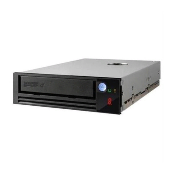
Sony GY-8240FC Operation Manual (92 pages)
DTF Tape Drive
Brand:
Sony
| Category:
Storage
| Size: 0.84 MB
Table of Contents
日本語
3
Table of Contents
3
Gy-8240Fc の主な特長
7
Dtfカセッ トの取り扱い
9
取り扱い上のご注意
9
装置の取り扱い
9
テレファイル
10
バーコードラベル
11
各部の名称と働き
12
基本的なセットアップ
15
接続
16
表示部のコントラストの調整
16
操作開始と終了
17
カセットの出し入れ
17
Dirカセッ トの再生
24
システム立ち上げ時の表示
25
操作中の表示
25
Hours Meter 表示
26
ワーニングコード
26
正常動作時のステータス表示
26
エラーメッセージ
27
エラーコード
28
エラー発生時の内部コマンド
30
Customメニュー
31
メニュー選択モード
31
メニューの使いかた
31
Diagメニュー
32
Updateメニュー
32
Setupメニュー
33
Romメニュー
39
Operationメニュー
40
ついて
41
クリーニング
41
定期メンテナンス
41
Gy-8240Fc
42
Dtf-2 テープレイアウト
43
トラックセットのレイアウト
43
Option-3 端子
44
Option-1/Option-2 端子
44
Fibre Channel 端子
44
ピン配置
44
Rs-232C の接続
45
English
48
Introduction
49
Terms
49
Features of the GY-8240FC
49
Notes on Handling the Unit and Media
51
On Handling the Unit
51
On Handling DTF Cassettes
51
Tele-File System
52
Bar Code Labels
53
Locations and Functions of Parts
54
Preparations
57
Basic Setup
57
Adjusting the Contrast of the Display Window
58
Connections
58
Operations
59
Start and End
59
Cassette Insertion and Removal
59
Format (DTF)
60
Load (DTF)
61
Unload (DTF)
62
Recovery (DTF)
65
Data Compression
65
Playback of DTF-1 Cassettes
66
Playback of dir Cassettes
66
Messages
67
Messages During Start-Up
67
Messages During Operation
67
Status Display in Normal Operation
68
Warning Codes
68
Hours Meter Indications
68
Error Messages
69
Error Codes
70
Internal Commands Upon Error Generation
73
Menu Operations
74
Menu Select Mode
74
CUSTOM Menu
74
DIAG Menu
75
UPDATE Menu
75
SETUP Menu
76
ROM Menu
83
OPERATION Menu
84
Maintenance
85
Head Cleaning
85
Regular Maintenance
85
Repacking
85
Specifications
86
Gy-8240Fc
86
DTF-2 Tape Layout
87
Track Set Layout
87
Pin Assignments
88
OPTION-1/OPTION-2 Connectors
88
OPTION-3 Connector
88
FIBRE CHANNEL Connectors
88
RS-232C Connection
89
Advertisement
Related Products
Sony GY-8240UWD
Sony GY-2120WD
Sony GY-2120WS
Sony Multiscan GDM-2000TC
Sony GDM-C520K Operating Instructions for MACINTOSH users
Sony GTK-X1BT
Sony XPERIA G3223
Sony GBL-T3
Sony GB-25A
Sony GDM-20SE
Sony Categories
Laptop
TV
CD Player
Camcorder
Digital Camera
More Sony Manuals
Login
Sign In
OR
Sign in with Facebook
Sign in with Google
Upload manual
Upload from disk
Upload from URL