Sign In
Upload
Manuals
Brands
Samsung Manuals
Air Conditioner
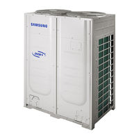
DVM S AM760FXVGNR
Samsung DVM S AM760FXVGNR Manuals
Manuals and User Guides for Samsung DVM S AM760FXVGNR. We have
1
Samsung DVM S AM760FXVGNR manual available for free PDF download: Installation Manual
Samsung DVM S AM760FXVGNR Installation Manual (113 pages)
Brand:
Samsung
| Category:
Air Conditioner
| Size: 9.45 MB
Table of Contents
Table of Contents
2
Severe Warning Signs
3
Safety Precautions
3
Checks before Installation and Service Work
4
Caution Signs
5
Do Not Install the Product in Following Places
5
Outdoor Unit Classification
6
Packaging Material Disposition
6
Preparing for Installation
6
Outdoor Unit Combination
7
Standard Type (Heat Pump)
7
Preparing for Installation - Tables
8
When Moving with a Forklift
17
When Moving Product Without Wooden Pallet and Crane Is Not Available
17
Moving the Outdoor Unit
17
When Moving with a Crane
17
Caution When Installing the Product in Seashore
18
Selecting Installation Location
18
Single Installation
21
Space Requirement for Installation
21
Module Installation
22
Accessories
23
Base Ground Construction
24
Base Construction and Installation of the Outdoor Unit
24
Outdoor Unit Installation
25
Outdoor Unit Base Mount and Anchor Bolt Position
25
Examples of Draining Work
26
Cautions Regarding on Connecting the Anchor Bolt
27
Cautions Regarding on Connecting the Pipe
27
Cautions Regarding on Anti-Vibration Frame Installation
27
Caution for Installing Discharge Duct
28
Installing the Outdoor Unit Around the Obstacles
28
Installing the Wind/Snow Prevention Duct
28
Cautions Regarding Installing the Frame and Selecting the Base Ground
29
Installing the Outdoor Unit in Cold Region
29
Installing the Outdoor Unit in Windy Region
30
Refrigerant Pipe Installation
31
Selecting Refrigerant Pipe
32
Size of the Pipe Connected to the Outdoor Unit
33
Size of the Pipe between Branch Joints
34
Size of the Pipe between the Branch Joint and the Indoor Unit
34
Branch Joint
35
Y-Joint
35
Distribution Header
35
H/R
36
Branch Joint between Outdoor Units
38
First Branch Joint
38
Amount of Additional Refrigerant Depending on the Pipe Size
39
Additional Refrigerant
39
Basic Amount of Refrigerant Within the Outdoor Unit
39
Amount of Additional Refrigerant for each Indoor Unit
40
Method to Calculate Total Amount of Additional Refrigerant
41
Example of Refrigerant Calculation for HP Models
42
Temper Grade and Minimum Thickness of the Refrigerant Pipe
43
Keeping Refrigerant Pipe
44
Refrigerant Pipe Welding and Safety Information
44
Nitrogen Flushing Welding
44
Direction of the Pipe When Welding
44
Cutting or Flaring the Pipes
45
Connecting the Flared Pipes
46
Pipe Installation for an Outdoor Unit
47
Direction of the Pipe
47
Caution for Using Knock-Out Hole
47
Connecting Refrigerant Pipe for Outdoor Unit
48
Caution for Welding the Pipe to an Outdoor Unit
48
Pipe Installation between the Outdoor Units
49
Examples of Refrigerant Pipe Installation
50
Allowable Length of the Refrigerant Pipe and the Installation Examples
51
Installing the Branch Joints
56
Installing the Distribution Header
57
Installing the Branch Joint between Outdoor Units
58
Installation of Outdoor Joints
58
Install the Distribution Header Horizontally
58
Installing the MCU
60
MCU Specification
60
Installing the Indoor Units
61
How to Connect the Pipes
62
Specification of the Circuit Breaker and Power Cable
63
Electrical Wiring Work
63
Caution for Electrical Work
66
Power and Communication Cable Configuration
67
Specification of the Protection Tube
68
Caution for Perforating the Knock-Out Hole
68
Power Wiring Diagram
69
Selecting Solderless Ring Terminal
71
Connecting the Power Terminal
72
Examples of How to Use the Cable Striper
73
Fixing the Power Cable
74
Connect the Ring Terminal of 3 Phase Cable
74
Fixing the Ground Cable
75
Withdrawing the Power Cable
75
Installing the Solution Device
76
Connecting the MCU
77
Grounding Work
79
Grounding the Power Cable
79
Air Tightness Test and Vacuum Drying
80
Vacuum Drying Pipes and Indoor Units
81
Insulating the Refrigerant Pipes and Branch Joints
82
Selecting the Refrigerant Pipe Insulator
82
Pipe Insulation
82
Insulate the Refrigerant Pipe
83
Insulate the Distribution Header
84
Insulating the Branch Joint
84
Insulating the Pipe Located Inside of the Outdoor Unit
85
Charging Refrigerant (for the Turkish Market Only)
85
Using Service Valve for Gas
87
Basic Segment Display
88
Setting Outdoor Unit Option Switch and Key Function
88
Setting Outdoor Unit Option Switches: B Type
89
Setting Outdoor Install Option
89
Installing and Setting the Option with Tact Switch
90
Setting Key Operation and Checking the View Mode with Tact Switch
94
Setting the MCU Address and the MCU Ports to Use
98
Setting the MCU and Pipe Addresses (for HR Only)
98
Setting the Pipe Addresses Manually
99
Setting the Pipe Addresses Automatically (Auto Pipe Pairing Operation)
100
Check Items before Running the Auto Pipe Pairing Operation
100
To Run the Auto Pipe Pairing Operation
101
Things to Check after Completing the Installation
102
Checklist before Auto Trial Operation
104
Inspection and Test Operation
104
Auto Trial Operation
105
Inspection and Trial Operation
106
Measure to Take When E503 Error Occurs
106
Measure to Take When E505, E506 Error Occurs
108
Automatic Refrigerant Amount Detection Function
110
Advertisement
Advertisement
Related Products
Samsung AM760KXVAGH1ET
Samsung AM760MXVGNR3ET
Samsung AM760MXVGNR4ET
Samsung AM760JXVAGH1
Samsung AM760JXVHGH1
Samsung AM760JXVHGH2
Samsung AM760JXVHGR1
Samsung AM760JXVAFH1AZ
Samsung DVM S AM760MXVAFC1AZ
Samsung DVM S AM760MXVAJC2AZ
Samsung Categories
Cell Phone
Monitor
Microwave Oven
Air Conditioner
LCD TV
More Samsung Manuals
Login
Sign In
OR
Sign in with Facebook
Sign in with Google
Upload manual
Upload from disk
Upload from URL