Sign In
Upload
Manuals
Brands
Samsung Manuals
Air Conditioner
DVM Plus 2 Series
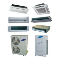
User Manuals: Samsung DVM Plus 2 Series Air Conditioner
Manuals and User Guides for Samsung DVM Plus 2 Series Air Conditioner. We have
2
Samsung DVM Plus 2 Series Air Conditioner manuals available for free PDF download: Service Manual
Samsung DVM Plus 2 Series Service Manual (522 pages)
Brand:
Samsung
| Category:
Air Conditioner
| Size: 24.66 MB
Table of Contents
Service Manual
1
Table of Contents
2
11 Precautions
8
Safety Precautions
8
Warning
9
Caution
10
Product Specifications
11
Way Cassette Type
13
Mini 4 Way Cassette
17
Wall-Mounted Type(Premium)
20
Wall-Mounted Type(Prestige)
21
Ceiling Type
22
Product Specifications
23
Outdoor Unit
37
Accessory
45
Alignment and Adjustments
49
Way Cassette Type
51
Duct Type(Low Silhouette, High Pressure, Built-In)
53
Ceiling Type
55
Setting Option Setup Method
57
Option Code
62
Disassembly and Reassembly
63
Way Cassette Type
72
Way Cassette Type
80
Mini 4 Way Cassette Type
88
Duct Type(Low Silhouette)
97
Duct Type(High & Low Pressure)
103
Duct Type(Built-In)
106
Duct Type(Slim)
110
Wall-Mounted Type(Premium)
115
Wall-Mounted Type(Prestige)
118
Ceiling Type
122
Outdoor Unit
131
4/5/6Hp
131
8/10Hp
133
12/14Hp
136
Exploded Views and Parts List
139
Indoor Unit
139
Way Cassette Type
139
Way Cassette Type
143
Way Cassette Type
147
Mini 4 Way Cassette Type
153
Duct Type(Low Silhouette)
157
Duct Type(High & Low Pressure)
159
Duct Type(Built-In)
160
Duct Type(Built-In)
163
Duct Type(Slim1)
167
Duct Type(Slim2)
169
Wall-Mounted Type(Premium)
171
Wall-Mounted Type(Prestige)
177
Ceiling Type
185
Outdoor Unit
189
4/5/6Hp
189
8/10Hp
193
12/14Hp
197
Electrical Parts List
201
Indoor Unit
201
Way Cassette Type
201
Way Cassette Type
207
Way Cassette Type
213
Mini 4 Way Cassete Type
219
Duct Type(Low Silhouette & Built-In)
222
Duct Type(High & Low Pressure)
228
Duct Type(Slim 1)
234
Duct Type(Slim 2)
237
Wall-Mounted Type(Premium)
243
Wall-Mounted Type(Prestige)
248
Ceiling Type
254
Outdoor Unit
260
Rvxmfh040E
260
Rvxmfh050E
265
Rvxmfh050G
270
Rvxmfh060G
276
Rvxvht080G✳/Rvxfht080G
282
Rvxvht100G✳/Rvxfht100G
290
Rvxvht120G✳/Rvxfht120G
298
Rvxvht140G✳/Rvxfht140G
307
Outdoor Power PCB
316
Outdoor CT PCB
319
Wiring Diagram
322
Indoor Unit
322
Way Cassette Type
322
Way Cassette Type
323
Way Cassette Type
324
Mini 4 Way Cassette Type
325
Duct Type(Low Silhouette, Built-In)
326
Duct Type(High & Low Pressure)
327
Duct Type(Slim1, Slim2)
328
Duct Type(Slim3)
329
Wall-Mounted Type(Premium)
330
Wall-Mounted Type(Prestige)
331
Ceiling Type
332
Outdoor Unit
333
Phase 4HP
333
Phase 5HP
334
Phase 5/6HP
335
8/10Hp
336
12/14Hp
337
Schematic Diagram
338
Indoor Unit
338
Way Cassette Type
338
Way Cassette Type
339
Way Cassette Type
340
Mini 4 Way Cassette Type
341
Duct Type
342
Wall-Mounted Type
343
Ceiling Type
344
Outdoor Unit (Mini DVM Series)
345
Outdoor Unit (DVM Plus2 Series)
346
Main Pcb 1
346
Main PCB
346
Main Pcb 2
347
Power Pcb
348
Refrigerant Circuit Diagram
349
Cooling Operation
349
Heating Operation
352
A Description of Cycle Function Parts
355
PCB Diagram
357
Indoor Unit
357
Way Cassette Type
357
Way Cassette Type
359
Way Cassette Type
361
Mini 4 Way Cassette Type
363
Duct Type(Low Silhouette/Built-In)
365
Duct Type(High & Low Pressure)
367
Duct Type(Slim)
369
Wall-Mounted Type(Premium)
371
Wall-Mounted Type(Prestige)
373
Ceiling Type
375
Outdoor Unit (Mini DVM Series)
377
Outdoor Unit (DVM Plus2 Series)
378
Main Pcb_Ac
378
Main Pcb_Dc
379
Power Pcb
380
Ct Pcb
381
Operating Instructions and Installation
382
Mini-DVM System
382
Features
382
Installation
386
DVM Plus2 System
388
Features
388
Technology
393
Installation
404
Installing the Refrigerant Pipe Work
406
Troubleshooting
412
Operating Flow of Outdoor Unit
412
Initial Tracking (Communication Check) - Indicated if Abnormal
413
Reverse Phase/Missing Phase Detection (Outdoor Unit Using 3 Phase Power)
414
Indicated if Abnormal
414
Compressor Preheating - Indicated
416
Self Diagnosis by Indoor Unit LED (Display Lamp) Display
417
Self Diagnosis by Outdoor Unit Error Display
419
Error Display Method
419
Outdoor Unit Fan Motor Rpm Error
442
Outdoor Temperature Sensor Error
451
Eeprom Error
459
Block Diagram
485
Indoor Unit
485
Way Cassette Type
485
Way Cassette Type
486
Way Cassette Type
487
Mini 4 Way Cassette Type
488
Duct Type(Built-In/High & Low Pressure)
489
Duct Type(Slim)
490
Wall-Mounted Type(Premium)
491
Wall-Mounted Type(Prestige)
492
Ceiling Type
493
Outdoor Unit (Mini DVM Series)
494
Power PCB
496
Reference Information
497
Index for Model Name
497
Indoor Unit
497
Outdoor Unit
498
Special Operation Mode (Mini DVM Series)
499
The Setting of Option Switch
499
The Function of Key on the Outdoor Unit PCB
500
Test Operation
502
Special Operation Mode (DVM Plus2 Series)
505
Refrigerant Collection Operation
505
Pump down
505
Pump out
509
Oil Collection Operation
510
Vacuum Preparing Operation
511
Filter Drier Equipping Method When Compressor Is Breakdown
512
Information of Refrigerant R410A
513
Calculation for Additional Refrigerant
515
Exclusive Tools, Only R410A
516
Q & a for Non-Trouble
517
Advertisement
Samsung DVM Plus 2 Series Service Manual (335 pages)
Brand:
Samsung
| Category:
Air Conditioner
| Size: 49.72 MB
Table of Contents
Service Manual
1
Table of Contents
2
11 Precautions
6
Safety Precautions
6
Warning
7
Caution
8
Product Specifications
9
The Feature of Product
9
Convenient Installation
10
4-Way Cassette Type
11
Duct Type
15
Wall-Mounted Type (Premium)
17
Wall-Mounted Type (Prestige)
18
Ceiling Type
19
Product Specifications
20
Outdoor Unit
33
Accessories
41
Alignment and Adjustments
45
Error Mode and Check Method
45
Way Cassette Type
47
Duct Type(Low Silhouette, High Pressure, Built-In)
49
PCB Option Code Input Method
53
Setting Option Setup Method
53
Option Code
58
15 Exploded Views and Parts List
59
1-Way Cassette Type
59
Indoor Unit Disassembly and Reassembly
59
2-Way Cassette Type
68
4-Way Cassette Type
76
Duct Type(Low Silhouette)
84
Duct Type(High & Low Pressure)
90
Duct Type(Built-In)
93
Duct Type(Slim)
97
Wall-Mounted Type(Premium)
102
Wall-Mounted Type(Prestige)
105
Ceiling Type
109
Outdoor Unit Disassembly and Assembly
118
Exploded Views and Parts List
127
Way Cassette Type
131
Way Cassette Type
135
Duct Type(Low Silhouette)
141
Duct Type(High & Low Pressure)
143
Duct Type(Built-In)
147
Duct Type(Slim1)
151
Duct Type(Slim2)
153
Wall-Mounted Type(Premium)
155
Wall-Mounted Type(Prestige)
161
Ceiling Type
169
Outdoor Unit (DVM Plus2 Series)
173
8/10Hp
178
12/14Hp
181
17 Schematic Diagram
185
Wiring Diagram
185
1-Way Cassette Type
185
2-Way Cassette Type
186
4-Way Cassette Type
187
Duct Type
188
Wall-Mounted Type
189
Wall-Mounted Type(Prestige)
190
Ceiling Type
191
Outdoor Unit (Mini DVM Series)
192
Phase 5HP
193
Phase 5/6HP
194
Schematic Diagram
198
19 PCB Diagram
198
Indoor Unit
198
1-Way Cassette Type
198
Way Cassette Type
199
4-Way Cassette Type
200
Duct Type
201
Wall-Mounted Type
202
Ceiling Type
203
Outdoor Unit (Mini DVM Series)
204
Refrigerant Circuit Diagram
208
Cooling Operation
208
Heating Operation
211
Description of Cycle Function Parts
214
PCB Diagram
217
Way Cassette Type
219
Way Cassette Type
221
Duct Type(Low Silhouette/Built-In)
223
Duct Type(High & Low Pressure)
225
Duct Type(Slim)
227
Wall-Mounted Type(Premium)
229
Wall-Mounted Type(Prestige)
231
Ceiling Type
233
Outdoor Unit (Mini DVM Series)
235
Outdoor Unit (DVM Plus2 Series)
236
Main Pcb_Ac
236
Main Pcb_Dc
237
Power Pcb
238
Ct Pcb
239
Operating Instructions and Installation
240
Feature
240
DVM Plus2
240
Various Capacity and 21 Combinations with Multi Module System
240
Minimized Installation Space
241
Reduction of Unit Weight
241
Wide Range of Cooling and Heating Operation
242
Long Piping
242
Oil Balance Distributor
243
Small Connection Pipe
243
Back up Function
244
Technology
245
DVM (Digital Variable Multi)'S
245
The Performance of the Digital Scroll Compressor
245
Pressure Chamber of the Digital Scroll Compressor
245
Pulse Width Modulation (PWM)
246
The PWM to Control the Cooling System Automatically
246
EEV (Electronic Expansion Valve): Optimized Refrigerant Control
247
High Energy Efficiency
248
Unloaded Power Consumption Is Only 10% of Full Load Power
248
Efficient Cooling and Heating System
248
Multi-Evaporator Saving Energy
249
Modulated Compressor Matching Supply and Demand
249
Energy Saving
250
Cooling COP Comparison with Inverter
251
Heat Exchanger Technology
252
Advantages for Installation and Maintenance
253
Cost Saving
253
Long Pipe Runs for Easy Installation and Application
253
High Elevation Reliability
254
Space Saving
255
Installation
256
Locating the Units
256
Outdoor Unit Combination
256
Overall System Configuration
257
Installing the Refrigerant Pipe Work
258
Selecting the Refrigerant Pipe
258
Allowable Length of the Refrigerant Pipe and the Installation Examples
259
Select the First Y-Joint Depending on the Outdoor Unit Capacity
261
Selecting Additional Refrigerant Charge
263
Troubleshooting
264
Operating Flow of Outdoor Unit
264
Initial Tracking (Communication Check)
265
Cooling Only
265
Installed Indoor Unit Numbers Setting Switch
266
Reverse Phase/Missing Phase Detection
267
Compressor Preheating
268
Self Diagnosis by Indoor Unit LED (Display Lamp) Display
269
Self Diagnosis by Outdoor Unit Error Display
271
Error Display Method
271
The Meaning of First Alphabet of the Error Number
271
Error Display Sequence
271
Prohibit Compressor Starting According to the Outdoor Temperature
274
Prohibit Starting by Low Pressure
275
Oil Valve(Equal Oil Valve) 1 Self Diagnosis
276
Comp down by High Pressure Protection Control
277
Comp down by Low Pressure Protection Control
278
Comp down by Indoor Unit Freezing Protection Control
279
Compressor Sump Temperature Protection Control
280
Comp down by Compressor Emission Temperature Sensor
281
COND out Sensor Breakaway
282
Suction Temperature Sensor Breakaway
283
Compressor over Current Error
284
Detection of Floating Switch of Indoor Unit Drain Pump
286
Indoor Unit EV Close Error
287
Indoor Unit EV Open Error
288
Indoor Heat Exchanger EVAP in Sensor Breakaway
289
Indoor Heat Exchanger EVAP out Sensor Breakaway
290
Compressor Sump Temperature (Oil Temperature) Sensor Breakaway
291
Compressor Emission Temperature Sensor Breakaway
292
Compressor Low Current Error
293
Outdoor Unit Fan Motor High Temperature Error
294
Outdoor Unit Fan Motor RPM Error
294
Outdoor Unit Fan Motor IPM High Temperature Error
295
Outdoor Unit Fan Motor over Current Error
295
Outdoor Unit Fan Motor Reverse Rotation Error
296
Indoor Unit Room Temperature Sensor Error (Open/Short)
297
Indoor Unit EVAP in Sensor Error (Open/Short)
298
Indoor Unit EVAP out Sensor Error (Open/Short)
299
Communication Error between Indoor Unit and Outdoor Unit
301
Outdoor Temperature Sensor Error
303
Digital Compressor Discharge Temperature Sensor Error (Open/Short)
304
Constant Speed Compressor Discharge Temperature Sensor Error
305
High Pressure Sensor Error (Open/Short)
306
Low Pressure Sensor Error (Open/Short)
306
Oil Temperature Sensor/Equal Oil Temperature Sensor Error (Open/Short)
307
COND out Temperature Sensor Error (Open/Short)
308
Dual-Pipe Temperature Sensor Error (Open/Short)
309
Detection of Reverse Phase, Missing Phase of 3 Phase Power
310
Instant Power-Off Error
311
EEPROM Error
311
Communication Error between the Outdoor Unit Main and Sub MICOM
312
Communication Error between the Outdoor Units
312
Block Diagram
313
Indoor Unit
313
1-Way Cassette Type
313
2-Way Cassette Type
314
4-Way Cassette Type
315
Duct Type(Built-In/High & Low Pressure)
316
Duct Type(Slim)
317
Wall-Mounted Type(Premium)
318
Wall-Mounted Type(Prestige)
319
Ceiling Type
320
Outdoor Unit (Mini DVM Series)
321
Main PCB
321
Power PCB
323
Reference Information
324
Special Operation Mode
324
Refrigerant Collection Operation
324
Pump down
324
Pump out
326
Oil Collection Operation
327
Operation Setup Key and Display (in Outdoor Unit)
327
Oil Collection During Cooling Operation
327
Oil Recovery in the Heating
328
Vacuum Preparing Operation
328
Make the Condition of the Outdoor Unit Vacuum Preparing Operation
328
Information of Refrigerant R410A
329
Thermodynamic Characteristic of R410A
330
Calculation for Additional Refrigerant
331
Exculsive Tools, Only R410A
332
Advertisement
Related Products
Samsung DVM PLUS III HR RD075VRXFA
Samsung DVM PLUS III HR RD100VRXFA
Samsung DVM PLUS III HR RD125VRXFA
Samsung P4SMA
Samsung PMSMA
Samsung PH45ZV
Samsung PH28ZV
Samsung PC4NUSKAN
Samsung PC4SUSMC
Samsung PC4SUSMF
Samsung Categories
Cell Phone
Monitor
Microwave Oven
Air Conditioner
LCD TV
More Samsung Manuals
Login
Sign In
OR
Sign in with Facebook
Sign in with Google
Upload manual
Upload from disk
Upload from URL