Sign In
Upload
Manuals
Brands
Mitsubishi Electric Manuals
Inverter
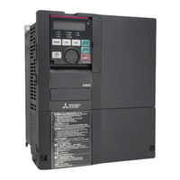
FR-A860-03360
Mitsubishi Electric FR-A860-03360 Manuals
Manuals and User Guides for Mitsubishi Electric FR-A860-03360. We have
1
Mitsubishi Electric FR-A860-03360 manual available for free PDF download: Instruction Manual
Mitsubishi Electric FR-A860-03360 Instruction Manual (727 pages)
600V CLASS SPECIFICATION INVERTER
Brand:
Mitsubishi Electric
| Category:
Inverter
| Size: 26.28 MB
Table of Contents
5.3 Speed Control under Real Sensorless Vector Control, PM Sensorless Vector Control 147
6
Table of Contents
6
2 Installation and Wiring
18
Peripheral Devices
19
Covers
22
Removal and Reinstallation of the Front
22
Installation of the Inverter and Enclosure Design
25
Terminal Connection Diagrams
33
Main Circuit Terminals
35
Control Circuit
44
Communication Connectors and Terminals
57
Connection of Motor with Encoder (Vector Control)
61
Parameter Settings for a Motor with Encoder
65
Connection of Stand-Alone Option Units
66
3 Precautions for Use of the Inverter
68
Electro-Magnetic Interference (EMI) and Leakage Currents
69
Installation of a Reactor
72
Power Supply Harmonics
72
Power-OFF and Magnetic Contactor (MC)
73
Countermeasures against Deterioration of the 600 V Class Motor Insulation
74
Checklist before Starting Operation
75
Failsafe System Which Uses the Inverter
77
4 Basic Operation
80
Frequently-Used Parameters (Simple Mode Parameters)
81
Basic Operation Procedure (PU Operation)
83
Basic Operation Procedure (External Operation)
87
Basic Operation Procedure (JOG Operation)
93
Speed Control under Real Sensorless Vector Control, Vector Control, PM Sensorless Vector Control
148
Setting Procedure of Real Sensorless Vector Control (Speed Control)
151
Setting Procedure of Vector Control (Speed Control)
153
Setting Procedure of PM Sensorless Vector Control (Speed Control)
154
Setting the Torque Limit Level
155
Control and PM Sensorless Vector Control)
165
Troubleshooting in the Speed Control
172
Speed Feed Forward Control and Model Adaptive Speed Control
174
Torque Bias
176
Avoiding Motor Overrunning
180
Notch Filter
182
Torque Control under Real Sensorless Vector Control and Vector Control
183
Setting Procedure of Real Sensorless Vector Control (Torque Control)
188
Setting Procedure for Vector Control (Torque Control)
190
Torque Command
191
Speed Limit
196
Torque Control Gain Adjustment
202
Troubleshooting in Torque Control
203
Torque Control by Variable-Current Limiter Control
204
Position Control under Vector Control
205
About Position Control
205
Setting Procedure of Vector Control (Position Control)
207
Simple Positioning Function by Parameters
208
Position Control by the FR-A8AL Pulse Train Input
223
Position Control by Inverter Pulse Train Input
226
Clear Signal Selection
227
Pulse Monitor
228
Electronic Gear Setting
233
Position Adjustment Parameter Settings
235
Position Control Gain Adjustment
237
Troubleshooting in Position Control
238
Real Sensorless Vector Control, Vector Control, PM Sensorless Vector Control Adjustment
240
Speed Detection Filter and Torque Detection Filter
240
Excitation Ratio
241
Gain Adjustment of Current Controllers for the D Axis and the Q Axis
241
E) Environment Setting Parameters
242
Real Time Clock Function
243
Reset Selection/Disconnected PU Detection/Pu Stop Selection
245
PU Display Language Selection
248
Buzzer Control
248
PU Contrast Adjustment
249
Extended Direct Setting
249
Resetting USB Host Errors
250
Multiple Rating Setting
250
Parameter Write Selection
252
Password Function
254
Free Parameter
256
Setting Multiple Parameters as a Batch
256
Extended Parameter Display and User Group Function
260
Parameter Copy Alarm Release
261
PWM Carrier Frequency and Soft-PWM Control
262
Inverter Parts Life Display
263
Maintenance Timer Alarm
267
Current Average Value Monitor Signal
268
F) Setting of Acceleration/Deceleration Time and Acceleration/Deceleration Pattern 269 5.8.1 Setting the Acceleration and Deceleration Time
270
Acceleration/Deceleration Pattern
275
Remote Setting Function
280
Starting Frequency and Start-Time Hold Function
284
Minimum Motor Speed Frequency
285
Shortest Acceleration/Deceleration and Optimum Acceleration/Deceleration (Automatic Acceleration/Deceleration)
286
Lift Operation (Automatic Acceleration/Deceleration)
289
D) Operation Command and Frequency Command
291
Operation Mode Selection
292
Startup in Network Operation Mode at Power-ON
301
Start Command Source and Frequency Command Source During Communication Operation
302
Reverse Rotation Prevention Selection
309
Frequency Setting Via Pulse Train Input
309
JOG Operation
313
Operation by Multi-Speed Setting
315
H) Protective Function Parameter
317
Motor Overheat Protection (Electronic Thermal O/L Relay)
318
Fault Definition
324
Cooling Fan Operation Selection
325
Earth (Ground) Fault Detection at Start
326
Initiating a Protective Function
326
I/O Phase Loss Protection Selection
327
Retry Function
328
Limiting the Output Frequency (Maximum/Minimum Frequency)
330
Avoiding the Mechanical Resonance Points (Frequency Jump)
331
Stall Prevention Operation
333
Load Characteristics Fault Detection
340
Motor Overspeeding Detection
344
M) Monitor Display and Monitor Output Signal
345
Speed Display and Rotations Per Minute Setting
346
Monitor Indicator Selection Using Operation Panel or Via Communication
348
Monitor Display Selection for Terminals FM and am
358
Adjustment of Terminal FM and Terminal am
363
Energy Saving Monitor
366
Output Terminal Function Selection
371
Output Frequency Detection
380
Output Current Detection Function
383
Output Torque Detection
385
Remote Output Function
386
Analog Remote Output Function
387
Fault Code Output Selection
389
Pulse Train Output of Output Power
390
Detection of Control Circuit Temperature
391
Encoder Pulse Dividing Output
392
T) Multi-Function Input Terminal Parameters
393
Analog Input Selection
394
Analog Input Terminal (Terminal 1, 4) Function Assignment
398
Analog Input Compensation
399
Analog Input Responsiveness and Noise Elimination
401
Frequency Setting Voltage (Current) Bias and Gain
403
Bias and Gain for Torque (Magnetic Flux) and Set Voltage (Current)
408
Checking of Current Input on Analog Input Terminal
412
Input Terminal Function Selection
416
Inverter Output Shutoff Signal
419
External Fault Input Signal
420
Selecting Operation Condition of the Second Function Selection Signal (RT) and the Third Function Selection Signal (X9)
420
Start Signal Operation Selection
422
C) Motor Constant Parameters
424
Applied Motor
424
Offline Auto Tuning
427
Offline Auto Tuning for a PM Motor (Motor Constants Tuning)
437
Online Auto Tuning
445
Signal Loss Detection of Encoder Signals
447
A) Application Parameters
448
Electronic Bypass Function
449
Self Power Management
455
Brake Sequence Function
458
Start Count Monitor
463
Stop-On-Contact Control
464
Load Torque High Speed Frequency Control
467
Traverse Function
470
Anti-Sway Control
472
Orientation Control
474
PID Control
489
Changing the Display Increment of the Numerical Values Used in PID Control
502
PID Pre-Charge Function
505
Dancer Control
509
Automatic Restart after Instantaneous Power Failure/Flying Start with an Induction Motor
516
Offline Auto Tuning for a Frequency Search
523
Power Failure Time Deceleration-To-Stop Function
527
PLC Function
532
Trace Function
534
N) Operation Via Communication and Its Settings
542
Wiring and Configuration of PU Connector
542
Wiring and Configuration of RS-485 Terminals
544
Initial Setting of Operation Via Communication
547
Initial Settings and Specifications of RS-485 Communication
554
Mitsubishi Inverter Protocol (Computer Link Communication)
556
MODBUS RTU Communication Specification
570
USB Device Communication
585
Automatic Connection with GOT
586
Backup/Restore
587
G) Control Parameters
589
Manual Torque Boost
590
Base Frequency, Voltage
592
Load Pattern Selection
594
Excitation Current Low-Speed Scaling Factor
596
Energy Saving Control
598
Adjustable 5 Points V/F
599
DC Injection Brake, Zero Speed Control, and Servo Lock
600
Output Stop Function
606
Stop Selection
608
Regenerative Brake Selection and DC Feeding Mode
609
Regeneration Avoidance Function
615
Increased Magnetic Excitation Deceleration
618
Slip Compensation
619
Encoder Feedback Control
620
Droop Control
622
Speed Smoothing Control
625
Protective Functions
626
Reset Method for the Protective Functions
627
Inverter Fault and Alarm Indications
627
The List of Fault Displays
628
Causes and Corrective Actions
630
Check First When You Have a Trouble
649
Motor Does Not Start
649
Motor or Machine Is Making Abnormal Acoustic Noise
651
Inverter Generates Abnormal Noise
651
Motor Generates Heat Abnormally
652
Motor Rotates in the Opposite Direction
652
Speed Greatly Differs from the Setting
652
Acceleration/Deceleration Is Not Smooth
653
Speed Varies During Operation
653
Operation Mode Is Not Changed Properly
654
Operation Panel Display Is Not Operating
654
Motor Current Is too Large
654
Speed Does Not Accelerate
655
Unable to Write Parameter Setting
655
Power Lamp Is Not Lit
655
Precautions for Maintenance and Inspection
656
Inspection Item
657
Daily Inspection
657
Periodic Inspection
657
Daily and Periodic Inspection
658
Checking the Inverter Module and the Converter Module
660
Cleaning
660
Replacement of Parts
661
Removal and Reinstallation of the Control Circuit Terminal Block
666
Measurement of Main Circuit Voltages, Currents and Powers
667
Measurement of Powers
669
Measurement of Voltages
669
Measurement of Currents
669
Measurement of Inverter Input Power Factor
669
Measurement of Converter Output Voltage (Across Terminals P and N)
669
Measurement of Inverter Output Frequency
670
Insulation Resistance Test Using Megger
670
Pressure Test
670
Specifications
672
Inverter Rating
673
Common Specifications
675
Outline Dimension Drawings
677
Inverter Outline Dimension Drawings
677
Appendix
682
Appendix 1 for Customers Replacing the Conventional Model with this Inverter
683
Appendix 2 International Standards
684
Appendix 3 Specification Comparison between PM Sensorless Vector Control and Induction Motor Control
685
Appendix 4 Parameters (Functions) and Instruction Codes under Different Control Methods
686
Appendix 5 for Customers Using HMS Network Options
705
Advertisement
Advertisement
Related Products
Mitsubishi Electric FR-A860-00027
Mitsubishi Electric FR-A860-00090
Mitsubishi Electric FR-A860-00170
Mitsubishi Electric FR-A860-00320
Mitsubishi Electric FR-A860-00450
Mitsubishi Electric FR-A860-01670
Mitsubishi Electric FR-A860-04420
Mitsubishi Electric FR-A860-00680-04420-E
Mitsubishi Electric FR-A860-00027-00450-N6
Mitsubishi Electric FR-A860-00680-04420
Mitsubishi Electric Categories
Air Conditioner
Controller
Projector
Inverter
Heat Pump
More Mitsubishi Electric Manuals
Login
Sign In
OR
Sign in with Facebook
Sign in with Google
Upload manual
Upload from disk
Upload from URL