Sign In
Upload
Manuals
Brands
Mitsubishi Electric Manuals
Inverter
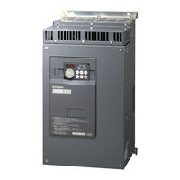
FR-A721-15K
Mitsubishi Electric FR-A721-15K Drives Manuals
Manuals and User Guides for Mitsubishi Electric FR-A721-15K Drives. We have
1
Mitsubishi Electric FR-A721-15K Drives manual available for free PDF download: Instrucion Manual
Mitsubishi Electric FR-A721-15K Instrucion Manual (217 pages)
Brand:
Mitsubishi Electric
| Category:
Inverter
| Size: 9.31 MB
Table of Contents
Table of Contents
3
Specifications
6
1 Outline
8
Product Checking and Parts Identification
8
Inverter and Peripheral Devices
9
Peripheral Devices
10
Method of Removal and Reinstallation of the
11
Installation of the Inverter and Enclosure Design
13
Inverter Installation Environment
13
Cooling System Types for Inverter Enclosure
16
Inverter Placement
17
2 Wiring
19
Terminal Connection Diagram
19
Main Circuit Terminal Specifications
20
Specification of Main Circuit Terminal
20
Terminal Arrangement of the Main Circuit Terminal, Power Supply and the Motor Wiring
21
Cables and Wiring Length
23
When Connecting the Control Circuit and the Main Circuit Separately to the Power Supply (Separate Power)
26
Control Circuit Specifications
27
Control Circuit Terminals
27
Changing the Control Logic
30
Control Circuit Terminal Layout
32
Wiring Instructions
33
When Connecting the Operation Panel Using a Connection Cable
33
Terminal Block
34
Communication Operation
34
Connection of Motor with Encoder (Vector Control)
35
Speed Control
38
Torque Control
38
Position Control
39
Initial Setting
40
3 Precautions for Use of the Inverter
42
EMC and Leakage Currents
42
Leakage Currents and Countermeasures
42
EMC Measures
44
Power Supply Harmonics
46
Harmonic Suppression Guideline
46
Power-Off and Magnetic Contactor (MC)
48
Inverter-Driven 400V Class Motor
49
Precautions for Use of the Inverter
50
Failsafe of the System Which Uses the Inverter
52
Failsafe of the System Which Uses the Inverter 45
53
4 Drive the Motor
54
Step of Operation
54
Operation Panel (FR-DU07)
55
Parts of the Operation Panel (FR-DU07)
55
Basic Operation (Factory Setting)
56
Operation Lock (Press [MODE] for an Extended Time (2S))
57
Monitoring of Output Current and Output Voltage
58
First Priority Monitor
58
Setting Dial Push
58
Change the Parameter Setting Value
59
Parameter Clear, All Parameter Clear
60
Parameter Copy and Parameter Verification
61
Operation Display
62
Before Operation
63
Simple Mode Parameter List
63
Overheat Protection of the Motor by the Inverter (Pr. 9)
64
When the Rated Motor Frequency Is 50Hz (Pr. 3)
65
Increase the Starting Torque (Pr. 0)
66
Limit the Maximum and Minimum Output Frequency (Pr. 1, Pr. 2)
67
Change Acceleration and Deceleration Time (Pr. 7, Pr. 8)
68
Selection of the Start Command and Frequency Command Locations (Pr. 79)
69
Large Starting Torque and Low Speed Torque Are Necessary (Advanced Magnetic Flux Vector Control, Real Sensorless Vector Control) (Pr. 71, Pr. 80, Pr. 81, Pr. 800)
70
Test Run
71
Higher Accuracy Operation Using a Motor with Encoder (Vector Control) (Pr.71, Pr.80, Pr.81, Pr.359, Pr.369, Pr.800)
73
To Exhibit the Best Performance of the Motor Performance (Offline Auto Tuning)
78
Operation Method
83
High Accuracy Operation Unaffected by the Motor Temperature (Online Auto Tuning) (Pr. 95)
83
To Perform High Accuracy/Fast Response Operation (Gain Adjustment of Real Sensorless Vector Control and Vector Control) (Pr. 818 to Pr. 821, Pr. 880)
84
Start/Stop from the Operation Panel (PU Operation Mode)
90
Set the Set Frequency to Operate (Example: Performing Operation at 30Hz)
90
Use the Setting Dial Like a Potentiometer to Perform Operation
91
Use Switches to Give a Start Command and a Frequency Command (Multi-Speed Setting)
92
Operation Mode
92
Perform Frequency Setting by Analog (Voltage Input)
93
Perform Frequency Setting by Analog (Current Input)
94
Make a Start and Stop with Terminals (External Operation)
95
Use the Set Frequency Set by the Operation Panel (Pr. 79 = 3)
95
Use Switches to Give a Start Command and a Frequency Command (Multi-Speed Setting) (Pr. 4 to Pr. 6)
96
External Operation
97
Perform Frequency Setting by Analog (Voltage Input)
98
Change the Frequency (60Hz) of the Maximum Value of Potentiometer (at 5V, Initial Value)
99
Perform Frequency Setting by Analog (Current Input)
100
Change the Frequency (60Hz) of the Maximum Value of Potentiometer (at 20Ma, Initial Value)
101
Parameter List
102
List of Parameters Classified by Purpose of Use
102
Parameter List
105
5 Troubleshooting
146
Reset Method of Protective Function
146
List of Fault or Alarm Display
147
Causes and Corrective Actions
148
Correspondences between Digital and Actual Characters
163
Check and Clear of the Faults History
164
Check First When You Have Troubles
166
Motor will Not Start
166
Motor Generates Abnormal Noise
166
Inverter Generates Abnormal Noise
167
Motor Generates Heat Abnormally
167
Motor Rotates in Opposite Direction
167
Speed Greatly Differs from the Setting
167
Acceleration/Deceleration Is Not Smooth
167
Motor Current Is Large
167
Speed Does Not Increase
167
The Motor and Machine Vibrate
167
Speed Varies During Operation
168
Operation Mode Is Not Changed Properly
168
Operation Panel (FR-DU07) Display Is Not Operating
168
POWER Lamp Is Not Lit
168
Parameter Write Cannot be Performed
168
6 Precautions for Maintenance and Inspection
169
Inspection Item
169
Daily Inspection
169
Periodic Inspection
169
Daily and Periodic Inspection
170
Display of the Life of the Inverter Parts
171
Checking the Inverter and Converter Modules
172
Cleaning
173
Replacement of Parts
173
Measurement of Main Circuit Voltages, Currents and Powers
176
Measurement of Powers
178
Measurement of Voltages and Use of PT
178
Measurement of Currents
179
Use of CT and Transducer
179
Measurement of Inverter Input Power Factor
179
Measurement of Converter Output Voltage (Across Terminals P/+ - N/-)
180
Measurement of Inverter Output Frequency
180
Insulation Resistance Test Using Megger
180
Pressure Test
180
7 Specifications
181
Rating
181
Inverter Rating
181
Motor Rating
183
Common Specifications
184
Outline Dimension Drawings
185
Inverter Outline Dimension Drawings
185
Dedicated Motor Outline Dimension Drawings
190
Installation of the Heatsink Portion Outside the Enclosure for Use
194
Protrusion of Heatsink
194
Appendices
196
Appendix 1 Main Differences and Compatibilities with the FR-A700 Series
196
Appendix 2 Instructions for UL and Cul Compliance
197
Appendix 3 Control Mode-Based Parameter (Function) Correspondence Table and Instruction Code List
199
Advertisement
Advertisement
Related Products
Mitsubishi Electric FR-A721
Mitsubishi Electric FR-A721-5.5K
Mitsubishi Electric FR-A721-7.5K
Mitsubishi Electric FR-A721-11K
Mitsubishi Electric FR-A721-18.5K
Mitsubishi Electric FR-A721-22K
Mitsubishi Electric FR-A721-30K
Mitsubishi Electric FR-A721-37K
Mitsubishi Electric FR-A721-45K
Mitsubishi Electric FR-A720-03460-NA
Mitsubishi Electric Categories
Air Conditioner
Controller
Projector
Inverter
Heat Pump
More Mitsubishi Electric Manuals
Login
Sign In
OR
Sign in with Facebook
Sign in with Google
Upload manual
Upload from disk
Upload from URL