Sign In
Upload
Manuals
Brands
Honeywell Manuals
Control Unit
CGW-MB
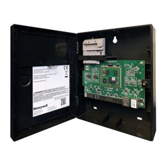
Honeywell CGW-MB Fire Alarm Gateway Manuals
Manuals and User Guides for Honeywell CGW-MB Fire Alarm Gateway. We have
1
Honeywell CGW-MB Fire Alarm Gateway manual available for free PDF download: Installation And User Manual
Honeywell CGW-MB Installation And User Manual (187 pages)
SOM Module
Brand:
Honeywell
| Category:
Control Unit
| Size: 3.42 MB
Table of Contents
Table of Contents
2
Section 1: General Information
7
About this Manual
7
Information Sources
7
1: Training Modules
7
2: Related Documents
7
Documentation Feedback
9
Revision History
9
Abbreviations Used
12
Approvals
13
User Information
14
Warnings and Cautions in this Manual
15
Disclaimer
15
Section 2: Overview
16
Operation
16
Honeywell Connected Life Safety Services
16
CLSS Gateway Mainboard Board Layout
16
1: Connecting Interfaces
17
2: LED Indicators
18
3: Switches on the CLSS Gateway Mainboard Board
20
CGW-MB Parts
20
Section 3: Security Recommendations
21
For Users
21
For Preventing Potential Risks
21
1: Unauthorized Access
21
User Access and Passwords
21
2: Memory Media
21
3: Software and Firmware Updates
22
4: Viruses and Other Malicious Software Agents
22
5: Network and Firewall Setup
22
Best Practices: Network Security
23
Best Practices: Connected Devices
23
6: Securing the Monitoring Stations
23
Section 4: Installation
24
Mounting the Portable CLSS Gateway Mainboard
24
1: Connecting to a Fire Alarm Panel
24
2: Connection Options
24
Section 5: Configurations
25
Commissioning the CLSS Gateway Mainboard
25
1: the Commissioning Steps
25
2: Exporting Panel's Topology Data
25
To Export the Topology Data
25
3: to Configure Via the Wireless Connection
25
Verifying the CLSS Gateway Mainboard Connections
28
Panel Brand and Connection Settings
29
1: to Change the Connection Settings
29
Honeywell CLSS Alarm Transmission Services
30
Communication Management
30
1: Central Station Communication
30
2: Activating the Central Station Communication
30
Adding a Central Station to the CLSS Account
30
Install a Fixed CLSS Gateway Mainboard at the Site
31
Configuring the Central Station Communication
31
Verifying the Central Station Communication Configurations
32
3: Dual Path Communication for Alarm Transmission
32
Supervision Period
32
Transmission Options
32
Section 6: Post-Installation Activities
33
Upgrading the CLSS Gateway Mainboard Firmware
33
1: to Upgrade before Commissioning the CLSS Gateway Mainboard
33
2: to Upgrade after Commissioning the CLSS Gateway Mainboard
34
3: to Locally Upgrade with a PC
35
4: to Verify the Upgrade
35
5: LED Indications During the Upgrade
35
Troubleshooting
36
1: to Troubleshoot LED-Indicated Issues
36
2: to Troubleshoot Other Issues
37
Section 7: Modbus Communications
39
Operation
39
Functionality
39
Recommended Cybersecurity Practices
39
Required Software
39
IP Requirements
39
1: IP Port Settings
39
2: IP Restrictions for the CLSS Gateway Mainboard
39
Bandwidth Calculation
40
Requirements for the Calculation
40
NFN Network
41
1: System Architecture
41
CGW-MB in NFN Network
42
2: Redundancy
43
Redundancy: for NFN Network
43
3: Legacy Modbus CLSS Gateway Mainboard
44
Replacing the Modbus CLSS Gateway Mainboard (Modbus-GW)
44
Using both the CGW-MB and the Modbus CLSS Gateway Mainboard
44
Agency Listings and Approvals
45
1: Agency Restrictions and Limitations
45
Standards
45
Underwriters Laboratories
45
Underwriters Laboratories Canada
45
National Fire Protection Association
45
Compatible Equipment
46
Mapping for Channels
47
1: Normal Mapping
47
2: Special Mapping
47
Modbus Feature Activation
48
1: to Purchase the Modbus Support
48
2: to Activate the Modbus Support
49
Installation and Configurations
50
The IP Settings
50
To Connect with the Modbus Client
50
To Configure the Modbus Settings
51
To Configure the Modbus Client
54
Modbus Command Support
54
Exception Responses
54
Modbus Addressing
54
CGW-MB Control Features
54
1: NOTIFIER UL: Supported Commands for NFN Network
54
2: Enabling the Control
55
3: Control Commands
55
Point Commands
55
Zone Commands
56
4: Sending Commands
56
For Panels of All Brands
56
For NOTIFIER UL
57
NOTIFIER UL: Analog Values and Trending
58
Analog Value Use Cases
58
Register Mapping
59
1: Register Mapping Overview
59
Channel Status Holding Registers
59
Point Status Holding Registers
60
2: Point Device Type Input Registers
61
3: Zones/Panel Circuits Status Holding Registers
62
4: Gamewell-FCI: CAM Text Event Holding Registers
63
5: Bell Circuits Status Holding Registers
64
6: Bell Circuits Device Type Input Registers
65
7: Panel Status Holding Register
66
Analog Values Input Registers
66
1: Panel and System Troubles Holding Registers
67
2: General Counters
67
3: CLSS Gateway Mainboard Information Input Registers
68
4: Node Status Details
68
Read Device Identification (0X2B/0X0E)
68
Troubleshooting
69
1: What Are some Basic Guidelines When Installing a CGW-MB
69
2: How Fast Can the Modbus Client Poll the CLSS Gateway Mainboard
69
3: How Can I Tell if the CLSS Gateway Mainboard Is Running
69
4: How Do I Recover a Lost Password from the CLSS Gateway Mainboard
69
5: What Is an "Initialization Read" for Analog Values
69
6: How Many Analog Values Can I Read at a Time
70
7: Why Do I Get an Exception Code When Trying to Read an Analog Value
70
8: Why Do I Get All Zeros When I Read an Analog Value
70
What Is the "Analog Value Polling Time out
70
Conversion to Modbus RTU
70
1: Hardware Configuration
70
2: Software Configuration
71
3: Connecting the Moxa Mgate MB3180 Interface
72
System Trouble
73
Exception Responses
73
CGW-MB Active Event Code
74
Device Types
76
System Troubles Register Map
78
Section 8: the Bacnet Feature
109
Agency Listings
109
1: Compliance
109
National Fire Protection Association
109
Underwriters Laboratories
109
Underwriters Laboratories Canada
109
Installation
109
Local
109
Canada
110
Compatible Equipment
110
CGW-MB Parts
111
System Requirements
111
System Architecture
111
1: IP Restrictions for the CLSS Gateway Mainboard
111
IP Requirements
112
IP Port Settings
112
1: Single Panel Architecture
112
2: Multi-Panel Network Architecture
113
Bacnet Feature Activation
114
1: to Purchase the Bacnet Support
114
2: to Activate the Bacnet Support
115
Configuring the Bacnet Network Settings
116
1: Installation and Configurations
116
2: the IP Settings
116
To Connect with the Bacnet Client
117
1: to Configure the Bacnet Settings
118
Replacing the BACNET-GW
121
Using both the CGW-MB and the Legacy Bacnet CLSS Gateway Mainboard
121
Bacnet PIC Statement
122
1: Protocol Implementation Conformance Statement (Normative)
122
Bacnet Protocol Revision: 14
122
Equations for Object Ids (Instance Numbers)
130
Appendix A: CLSS Gateway Mainboard Operating Conditions
134
A.1: Wirings and Power
134
Appendix B: Modulations and Power Used
135
Appendix C: Connecting to the Panels
136
C.1: CLSS Gateway Mainboard Board Connections
136
C.1.1: Connecting to a Fire Alarm Panel
138
Improving the Signal Fidelity
138
C.2: Supported Panels
139
C.3: am Series Panels
139
C.3.1: Connection Options
139
C.3.2: to Use an RS-232 Connection
139
C.4: ESSER Panels
141
C.4.1: Connection Options
141
C.4.2: to Use an RS 232 Connection
142
ESCOM Panels
142
C.4.3: to Use an RS-485 Connection
143
Flexes Panels
143
C.4.4: to Use an RS-232 Connection for Inventory Synchronization
144
C.4.5: to Use an RS232 Connection for Events
146
IQ8: Connecting through a Serial Interface Card
146
IQ8 Panels
148
To Use an RS-485 Connection
148
C.5: Farenhyt Panels
152
C.5.1: Connection Options
152
C.5.2: to Use an RS-485 Connection
152
C.5.3: Programming for Annunciator (ANN-PRI)
154
C.5.4: to Program for Annunciator
154
C.6: Firewarden Panels
155
C.6.1: Connection Options
155
C.6.2: to Use an RS-485 Connection
155
C.6.3: Programming for Annunciator (ANN-PRI)
157
C.6.4: to Program for Annunciator
157
To Verify the Changes
157
C.6.5: to Use Panel's Printer Port Connection
158
C.7: Gamewell-FCI Panels
160
C.7.1: Connection Options
160
C.7.2: to Use Panel's Printer Port Connection
160
C.8: Gent Panels
164
C.8.1: Connection Options
164
C.8.2: Compact Series Panels
164
To Use a RS-232 Connection
164
To Use a USB Connection
166
C.8.3: Vigilon Series Panels
168
To Use a UART/TTL Connection
168
To Use an RS-232 Port Via an I/O Card
168
To Use a USB Connection
170
C.9: Morley-IAS Panels
171
C.9.1: Connection Options
171
C.9.2: to Use an RS-232 Connection
171
C.10: Notifier® Ul
173
C.10.1: Connection Options
173
C.10.2: to Use a NUP Connection
173
C.11: NOTIFIER® European Panels (EN)
177
C.11.1: Connection Options
177
C.11.2: Preparing for Connections
177
C.11.3: to Use a NUP Connection
177
C.12: Silent Knight Panels
179
C.12.1: Connection Options
179
C.12.2: to Use an RS-485 Connection
179
C.12.3: Programming for Annunciator (ANN-PRI)
181
C.12.4: to Program for Annunciator
181
C.13: Triga Panels
182
C.13.1: Connection Options
182
C.13.2: to Use an RS-485 Connection
182
C.13.3: Programming for Annunciator (ANN-PRI)
184
C.13.4: to Program for Annunciator
184
C.14: VESDA® Detectors
185
C.14.1: Connection Options
185
C.14.2: to Use an Ethernet Connection
185
Before Connecting
185
Advertisement
Advertisement
Related Products
Honeywell CentraLine CLIOLR824A
Honeywell COILAB V Series
Honeywell COILCD V Series
Honeywell COILAB024V-000
Honeywell COILAB240V-000
Honeywell COILCD024V-000
Honeywell COILCD240V-000
Honeywell Maxon CMA11
Honeywell Maxon CMM11
Honeywell Maxon CMA12
Honeywell Categories
Thermostat
Controller
Control Unit
Security Camera
Accessories
More Honeywell Manuals
Login
Sign In
OR
Sign in with Facebook
Sign in with Google
Upload manual
Upload from disk
Upload from URL