Sign In
Upload
Manuals
Brands
GE Manuals
Power distribution unit
ALPS
GE ALPS Manuals
Manuals and User Guides for GE ALPS. We have
1
GE ALPS manual available for free PDF download: Instruction Manual
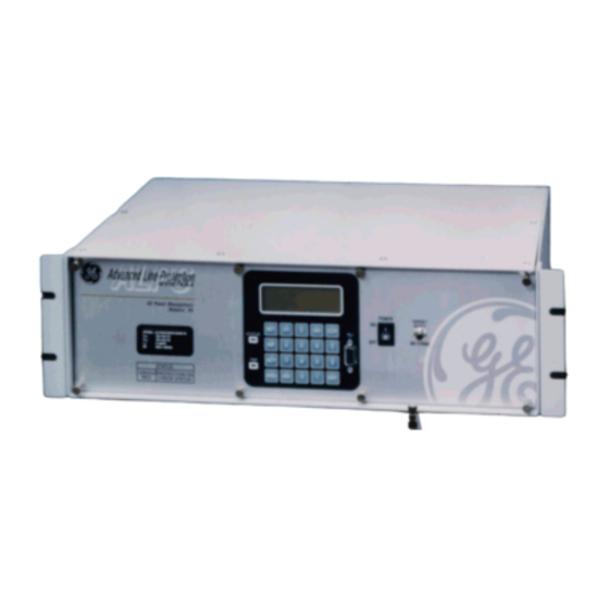
GE ALPS Instruction Manual (366 pages)
Advanced Line Protection System
Brand:
GE
| Category:
Power distribution unit
| Size: 4.94 MB
Table of Contents
Table of Contents
5
Inspection
13
Remote Communications Via Local Pc
14
Ordering
15
Description
16
1.2 Introduction
17
Ground Distance Quadrilateral Characteristics
17
Line Protection Schemes
20
Introduction
21
1.3 Custom Programmability
22
Configurable Outputs
22
1.4 Auxiliary Protection Functions
23
Potential Transformer Fuse Failure (Ptff)
23
Line Pickup
24
Remote-Open Detector
25
Out-Of-Step Blocking
26
1.5 Other Features
28
Flash Memory
28
Playback
29
Time Synchronization
30
Alarms
31
1.6 Communications
32
Keypad and Display
32
1.7 Self-Test Features
33
Start-Up Self-Tests
33
Continuous Monitor
34
Introduction
35
1.8 Protection Schemes
37
Permissive Underreach Transfer Trip (Putt)
37
Permissive Overreach Transfer Trip (Pott1)
39
Blocking Scheme
42
Hybrid Scheme
45
Single Phase Tripping
47
Description
50
1.9 Phase Idenitified Channel Schemes
52
Four Channel Phase Identified Channel Logic
52
Description
53
1.10 Out-Of-Step Tripping (Optional)
54
Out-Of-Step Detection
54
Two-Characteristic Operation
55
Description
56
Description
57
Recloser Inputs
58
Recloser Outputs
59
Synchronism Check (Optional)
60
Elementary Diagrams
61
2.2 General Settings
66
2.1 Introduction
66
Configuration
66
Communications
68
Oscillography
70
Programmable Inputs
72
2.3 Protection Settings
73
Z1Distance
73
Zone 2, Zone 3, and Zone 4 Distance Functions
77
Z2Distance
78
Z3Distance
80
Z4Distance
82
Cursupvisn
86
Overcurrnt
89
Voltage
91
Positive-Sequence Voltage Functions
92
Blk Reclos
93
Linepickup
94
Remoteopen
95
Lineovrld
96
Schmtimers
97
Line Info
100
Scada Dta
101
Os Blocking
102
Os Tripping
103
1.11 Compensated Positive Sequence Overvoltage (Optional)
105
Recloser
105
Noncrit_Al
110
2.5 Reference Tables
115
2.4 Inverse Curves
115
Index Numbers
115
Protection Settings Guide
121
General Settings Guide
128
Protection Settings Data Sheets
130
General Settings Data Sheets
137
Construction
139
Electrical Connections and Wiring
141
System Block Diagram
142
3.2 Installation
143
Receiving, Handling, and Storage
143
Warning
144
Magnetics Module
146
Communications Interface
147
Digital Output / Power Supply Board
148
Dsp / Ani / Comm / Lui
149
Cpu Board
150
Introduction
151
Equipment Grounding
152
Setting Changes
153
Entering Test Mode
154
4.2 General Relay Tests
157
T1 – Relay Status and Display Testing
157
T2 – Digital Output Test
158
T3 – Configurable Input and Output Test
159
T4 – Ac System Input Test
160
Description
163
5.2 Measuring Unit Tests
164
T1 – Fault Detector Test
164
T3 – Ib Blocking Supervision Test
165
T6 – Phase Instantaneous Overcurrent 50
166
Undervoltage Test
167
5.3 Zone Reach and Timer Tests
170
General Zone Reach Testing Considerations
170
T12 – Zone 2 Ground Reach, Mtg Ground Faults
171
T14 - Zone 4 Ground Reach, M4G Ground Faults
172
T15 – Ground (Zone Backup) Timer Tests
173
T16 – Zone 1 Phase Reach, M1 Faults
175
T18 – Zone 3 Phase Reach, M3 Faults
176
T19 – Zone 4 Phase Reach, M4 Faults
177
T20 – Phase (Zone Back-Up) Timer Tests
178
5.5 Mob Testing
181
T21 – Out-Of-Step Reach, Mob
181
Drawings and References
184
General Instructions
185
6.2 General Relay Tests
186
T1 – Lui Relay Status
186
T4 – Ac System Input Test
187
6.3 Measuring Unit Tests
188
Warning
188
T8 – Ground Directional Block Test, Ipb + Nb
189
6.4 Backup Protection Tests
190
T9 – Phase Instantaneous Overcurrent 50
190
T11 – Ground Time Overcurrent 51G
191
6.5 Zone Reach Tests
192
General Considerations
192
T12 – Zone 1 Ground Reach Test, M1G Ground Faults
194
T13 – Zone 2 Ground Reach, Mtg Ground Faults
195
T15 – Zone 4 Ground Reach, M4G Ground Faults
196
5.4 Phase-To-Phase Zone Reach Testing
198
T16 – Zone 1 Phase Reach, M1 Faults
198
T18 – Zone 3 Phase Reach, M3 Faults
199
10.2 Test Calculations
203
Description
203
Control Keys
204
Messages
205
Settings
206
End] Key
208
Edit General Settings
209
Actions
210
Enable Outputs
211
Relay Test
212
Channel Test
213
Keypad/Display Interface Test
214
Playback
215
Change Password
216
Enable/Disable Passwords
217
11.4 Connecting to and Logging out of a Device
218
Description
218
8.2 Information
219
Request Fault Information
219
Request Present Values
220
Event Information
221
Communication Passwords
223
Oscillography Snapshot
224
Ascii Interface
225
8.4 Remote Communication Interface
226
8.3 Ascii Interface
226
Hardware Switches
226
Pc Modem
227
Null-Modem Connections
229
Description
231
13.3 Creating Xpression Builder Logic
231
Description
233
9.2 Troubleshooting
234
Locating the Defective Board
234
Service System Status Failures
235
Description
237
Description
238
11.6 Information
238
Entering a Value
239
Mt Phase Units – Zone 2
240
M4 Phase Units – Zone 4
241
Mig Ground Units – Zone 1
242
M3G Ground Units – Zone 3
243
10.3 File Menu
244
New Test File
244
Close Test File
245
Save Input Quantities as
246
10.4 Edit Menu
247
Copy
247
Description
248
Description
249
Description
251
10.8 Help Menu
252
Contents
252
Overview
253
Software Installation
255
11.2 Using Alps-Link
257
Startup
257
Description
258
11.3 Setting up Your Host Machine
259
Printer Setup
259
Description
261
Settings
262
Actions
264
Description
266
Fault Report
267
Contact Status Report
268
11.7 Logging
269
Session Log
269
Retreive
270
Overview
277
Boolean Operators, Latches, Timers, & Counters
278
13.2 Xpression Builder Flags
280
Contact Converter Inputs
280
Description
285
Compiling and Downloading Xpression Builder Logic
287
Installation
289
Print Settings Report
291
Help Menu
292
Description
295
Communications Settings
295
Supported Modbus Functions
295
B.1.1 Description
295
Exception or Error Replies
296
Data Formats
296
Register Maps
297
B.2.1 Summary
297
Modbus Memory Map
299
Memory Map Data Formats
309
Description
310
C.1.1 Description
315
Modifying Settings Using Dnp
315
Device Profile
316
Dnp V3.00 Device Profile Document
316
Implementation Table
318
C.2.2 Implementation Table
318
Implementation Table Notes
319
Default Variations
319
Point Lists
320
Description
320
Binary Input, Binary Input Change
320
C.3.1 Description
320
Binary Output, Control Relay Output Block
325
Binary Counter, Frozen Counter
326
Analog Input, Analog Input Change
327
Analog Output, Analog Output Block
333
Data Formats - Analog Input and Output Points
340
Keypad Menus
343
Set Keypad Menu
343
Act Keypad Menu
344
Inf Keypad Menu
345
List of Figures
347
E.1.1 List of Figures
347
List of Tables
349
E.1.2 List of Tables
349
Warranty Information
351
Ge Power Management Warranty
351
Advertisement
Advertisement
Related Products
GE Allegro
GE AL-111X
GE Silent Alert 45137
GE Choice Alert 45129
GE Choice Alert 45131
GE Choice Alert 45138
GE Choice Alert 45314-1
GE AL-1291 Point ID
GE Alliance AL-3017
GE 745 TRANSFORMER MANAGEMENT RELAY
GE Categories
Refrigerator
Ranges
Microwave Oven
Air Conditioner
Dishwasher
More GE Manuals
Login
Sign In
OR
Sign in with Facebook
Sign in with Google
Upload manual
Upload from disk
Upload from URL