Sign In
Upload
Manuals
Brands
Fujitsu Manuals
Server
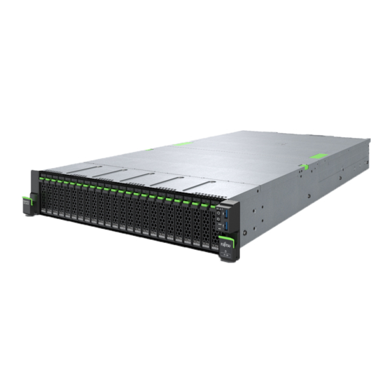
PRIMERGY RX2540 M7
Fujitsu PRIMERGY RX2540 M7 Manuals
Manuals and User Guides for Fujitsu PRIMERGY RX2540 M7. We have
1
Fujitsu PRIMERGY RX2540 M7 manual available for free PDF download: Upgrade And Maintenance Manual
Fujitsu PRIMERGY RX2540 M7 Upgrade And Maintenance Manual (646 pages)
Brand:
Fujitsu
| Category:
Server
| Size: 12.33 MB
Table of Contents
Version History
7
Table of Contents
7
1 Introduction
19
Concept and Target Groups of this Manual
19
Notational Conventions
19
2 Before You Start
21
Basic Information
21
Proceeding
21
Advanced Thermal Design (ATD)
21
Configuration Thermal Design (CTD)
22
Installing Optional Components
22
Replacing a Defective Component
23
Classification of Procedures
23
Assignment of Unit Categories
23
Customer Replaceable Units (CRU)
24
Upgrade and Repair Units (URU)
25
Field Replaceable Units (FRU)
26
Average Task Duration
27
Tools You Need at Hand
28
Documentation Overview
29
Downloading Manuals
29
List of Documents
29
3 Important Information
33
Introduction
33
Safety Instructions
33
Basic Safety Instructions
33
Before Starting up
34
Installation and Operation
34
Batteries
37
Working with Optical Disk Drives (Odds) and Media
37
Laser Information
39
Modules with Electrostatic-Sensitive Devices (ESD Modules)
39
Transporting the Server
41
Installing the Server in the Rack
42
Other Important Information
42
Energy Star
43
CE Conformity
43
FCC Class a Compliance Statement
44
Environmental Protection
45
Basic Hardware Procedures
47
Locating the Defective Server
47
Proceeding
47
Using Diagnostic Information
47
Determining the Error Class
48
Locating the Defective Component
48
Removing the Front Cover with Lock
49
Shutting down the Server
50
Disconnecting the Power Cord (DC PSU)
53
Disconnecting the Power Cord
50
Disconnecting the Power Cord (AC PSU)
50
Getting Access to the Component
55
Extending the Server out of the Rack
55
Safety Notes
55
Removing the Server from the Rack
56
Removing the Top Covers
58
Reassembling
59
Safety Notes
59
Installing the Top Covers
60
Installing the Server in the Rack
61
Sliding the Server into the Rack
64
Connecting the Power Cord
65
Connecting the Power Cord (AC PSU)
65
Connecting the Power Cord (DC PSU)
68
Installing the Front Cover with Lock
71
Switching on the Server
71
Handling Riser Modules
72
Removing a Riser Module
72
Installing a Riser Module
74
Handling the Fan Cage
76
Removing the Fan Cage
76
Installing the Fan Cage
77
Handling the Air Duct
79
Installing the Air Duct
79
Removing the Air Duct
80
Handling the Crossbar
83
Removing the Crossbar
83
Installing the Crossbar
84
Handling the Rear Air Grids
85
Removing a Rear Air Grid
85
Installing a Rear Air Grid
87
5 Basic Software Procedures
89
Validation
89
Starting the Maintenance Task
89
Suspending Bitlocker Functionality
89
Disabling the Boot Watchdog
90
Removing Backup and Optical Disk Media
92
Verifying and Configuring the Backup Software Solution
92
Switching on the ID Indicator
92
Checking Boot Priority
93
Completing the Maintenance Task
94
Updating or Recovering the BIOS and Irmc S6
94
Verifying System Information Backup or Restore
96
Updating Expansion Card Firmware
98
Reconfiguring the Backup Software Solution
99
Resetting the Boot Retry Counter
100
Enabling the Boot Watchdog
101
Enabling Replaced Components in the BIOS
102
Verifying the Memory Mode
103
Verifying the System Time Settings
104
Viewing and Clearing the System Event Log (SEL)
105
Updating the NIC Configuration File in a Linux and Vmware Environment
106
Resuming Bitlocker Functionality
107
Performing a RAID Array Rebuild
108
Basic Information
109
Looking for MAC/WWN/GUID and SAS Addresses
109
Looking for the MAC Address of a LAN Controller
110
Looking for the WWN Address of a Fibre Channel Controller
111
Looking for SAS Addresses of SAS Controllers for External Devices
112
Looking for the GUID Address of an Infiniband or Omni-Path Controller
112
Using the Chassis ID Prom Tool
113
Configuring LAN Teaming
115
Switching off the ID Indicator
116
Performing a Fan Test
117
Updating the Golden Image
117
Updating the Golden Image for Irmc S6 Firmware
117
Updating the Golden Image for BIOS Firmware
119
Setting Boot Priority
120
Recovering the Esxi Configuration Information Encryption Functionality
121
6 Power Supply Unit (PSU)
123
Safety Notes
123
Basic Information
123
Redundant Power Supply
126
Installing a Hot-Plug PSU
126
Removing a Hot-Plug PSU
129
Replacing a Hot-Plug PSU
133
7 Hard Disk Drive (HDD) / Solid State Disk (SSD)
135
Safety Notes
135
Basic Information
136
Handling Hdds or Ssds Without Installation Frame
138
Inch HDD and 3.5-Inch Installation Frame
138
Inch HDD/SSD and 2.5-Inch Installation Frame
140
Inch HDD/SSD and 3.5-Inch Installation Frame
141
Displaying HDD/SSD Slot Information
143
Inch HDD Configurations
146
Overview of Configurations
146
Configuration with up to 10 HDD Modules
146
Configuration with up to 12 HDD Modules
147
Installing 3.5-Inch HDD Modules
150
Removing 3.5-Inch HDD Modules
153
Replacing a 3.5-Inch HDD Module
156
Replacing the 10X 3.5-Inch HDD Backplane
158
Replacing the 12X 3.5-Inch HDD Backplane
161
Inch HDD/SSD Configurations
165
Overview of Configurations
165
Configuration with up to 16 HDD / SSD / Pcie SSD Modules
165
Configuration with up to 24 HDD / SSD / Pcie SSD Modules
170
Configuration with up to 24 Pcie SSD Modules
173
Installing 2.5-Inch HDD/SSD Modules
177
Removing 2.5-Inch HDD/SSD Modules
180
Replacing a 2.5-Inch HDD/SSD Module
183
Installing 2.5-Inch Pcie SSD Modules
185
Removing 2.5-Inch Pcie SSD Modules
188
Replacing a 2.5-Inch Pcie SSD Module
190
Replacing a 8X 2.5-Inch HDD Backplane
192
Replacing a 24X 2.5-Inch HDD Backplane and a Switch Board
198
SAS Expander Board
202
Installing the SAS Expander Board
202
Removing the SAS Expander Board
207
Replacing the SAS Expander Board
209
M.2 Ssd
211
Slots for M.2 Ssds on the M.2 Interposer Board
211
Installing an M.2 SSD
212
Removing an M.2 SSD
216
Replacing an M.2 SSD
218
Installing the M.2 Interposer Board
219
Removing the M.2 Interposer Board
222
Replacing the M.2 Interposer Board
225
Rear HDD/SSD Extension Box
227
Basic Information (Rear HDD/SSD)
227
Upgrading with Rear HDD Cage 1 and Rear HDD Cage
228
Upgrading with Rear HDD Cage 3
233
Replacing a Rear 2X 2.5-Inch HDD Backplane
236
Fans
241
Safety Notes
241
Basic Information
241
Replacing a Fan Module
243
9 Expansion Cards and Backup Units
245
Safety Notes
245
Basic Information
246
Handling Slot Brackets
249
Installing Slot Brackets
249
Removing Slot Brackets
252
Handling SFP+ Transceiver Modules
252
Installing SFP+ Transceiver Modules
252
Removing SFP+ Transceiver Modules
258
OCP (Open Compute Project) Modules
262
Position of the OCP Module
262
Installing an OCP Module
262
Removing an OCP Module
265
Replacing the OCP Module
266
Expansion Cards in Standard Pcie Slots
269
Installing an Expansion Card
269
Removing an Expansion Card
278
Replacing an Expansion Card
281
GPU Cards in Riser Modules
284
Installing a GPU Card in a Riser Module
284
Removing a GPU Card from a Riser Module
290
Replacing a GPU Card from a Riser Module
293
Replacing a Riser Card
295
Internal RAID Riser Module
297
Installing an Internal RAID Riser Module
297
Removing an Internal RAID Riser Module
303
Replacing an Internal RAID Riser Module
306
Replacing a Riser Card
307
Expansion Cards in Riser Modules
310
Installing an Expansion Card in a Riser Module
310
Removing an Expansion Card from a Riser Module
313
Replacing Expansion Cards from a Riser Module
315
Replacing a Riser Card
317
Flash Backup Unit (FBU)
320
Positions of the Fbus
320
Installing an FBU
321
Removing an FBU
326
Replacing an FBU
328
Main Memory
331
Safety Notes
331
Basic Information
332
Slots and Features
332
General Memory Population Rules
335
DDR5 Only - Memory Population Rules
337
Installing Memory Modules
341
Removing Memory Modules
344
Replacing Memory Modules
345
Handling Memory Dummy Modules
347
Processor (CPU)
349
Safety Notes
349
Basic Information
350
Upgrading to 2 Cpus Configuration
352
Handling the CPU Dummy Cover
362
Replacing a CPU or Heat Sink
365
12 Liquid Cooling (LC)
375
Safety Notes
375
Basic Information
375
Replacing the CPU for LC Device
376
13 Accessible Drives
389
Safety Notes
389
Basic Information
389
Optical Disk Drive (ODD)
391
Storing the ODD Latch
391
Installing the ODD (2.5-Inch Chassis)
391
Removing the ODD (2.5-Inch Chassis)
396
Replacing the ODD (2.5-Inch Chassis)
400
Installing the ODD (3.5-Inch Chassis)
402
Removing the ODD (3.5-Inch Chassis)
411
Replacing the ODD (3.5-Inch Chassis)
419
LTO Drive
420
Installing the LTO Drive
420
Removing the LTO Drive
428
Replacing the LTO Drive
435
RDX Drive
437
Installing the RDX Drive
437
Removing the RDX Drive
445
Replacing the RDX Drive
453
14 Thermal Sensor
455
Replacing the Thermal Sensor
455
Front Panel
463
Safety Notes
463
Basic Information
463
Common Operation Panel (COP)
464
Replacing the COP
464
Front VGA
470
Installing the Front VGA
470
Removing the Front VGA
473
Replacing the Front VGA
476
Additional Interfaces
479
Installing the Serial Interface
479
Safety Notes
479
Serial Interface
479
Removing the Serial Interface
482
Replacing the Serial Interface
484
Rear VGA Connector
485
Replacing the Rear VGA Connector
485
System Board and Components
489
Safety Notes
489
Basic Information
489
CMOS Battery
490
Replacing the CMOS Battery
490
Trusted Platform Module (TPM)
492
TPM Kit
492
Installing the TPM
493
Position of the TPM
493
Removing the TPM
497
Replacing the TPM
501
Installing the Irmc Microsd Card
504
Irmc Microsd Card
504
Note for Embedded Lifecycle Management (Elcm)
504
Removing the Irmc Microsd Card
506
Replacing the Irmc Microsd Card
507
Replacing the System Board
510
18 Appendix A Mechanical Overview
525
System Board
510
Inch HDD Configuration
525
Server Front
525
Inch HDD/SSD Configuration
526
Server Rear
527
Servers with Air Cooling
527
Servers with Liquid Cooling
529
Server Interior
530
Servers with Air Cooling
530
Servers with Liquid Cooling (LC)
531
Connectors and Indicators
532
Connectors and Indicators on the System Board
532
System Board D3983
532
Connectors on the Server Front
537
Server Front
537
Indicators on the COP
538
States of Power-On Indicator and Time Duration During Firmware Restore
541
Indicator on the ODD
544
Indicators on the RDX Drive
545
Indicators on Hot-Plug HDD / SSD / Pcie SSD Modules
546
Connectors on the Server Rear
547
Server Rear
547
ID, CSS and Global Error Indicators
549
LAN Indicators
551
Indicator on Hot-Plug PSU
553
Acoustic Indicators
554
Onboard Settings
555
Minimum Startup Configuration
556
19 Appendix B
559
Supplied Documents
559
Overview - English
561
Contents (Cont.1)
562
List of Cables
563
List of Cables (Cont.)
564
Basics
565
Common Operation Panel & Thermal Sensor
566
Ooptical Disk Drive / VGA 10X3.5"/16X 2.5
567
Serial Interface
568
RDX 16X 2.5
569
OOB & Power 10/12X3.5
570
OOB & Power 2X 8X 2.5" Bpl 1&2
571
OOB & Power 2X 8X 2.5" Bpl 1&3
572
OOB & Power 3X 8X 2.5" Bpl
573
OOB & Power 24X2.5" Nvme
574
Power Interposer Board @ Moboard
575
Power Expander Board
576
OOB & Power Rear 4X/6X HDD
577
Power GPU RTX A4500
578
Power GPU Power GPU A30/A40/RTX A6000/A100/A16/A30X/A100X
579
Power GPU H100
580
Data FBU Ep6Xx/Ep7Xx
581
HDD LED PRAID Cp6X0I/Ep6X0I/Ep780I
582
HDD LED PRAID Cp6X0I/Ep6X0I/Ep780I (Cont.)
583
HDD LED PRAID Ep325X-8I/16I
584
HDD LED PRAID Ep325X-8I/16I (Cont.)
585
Int. RAID Riser @ Moboard
586
SKD 1X / 2X
587
Onbaord SATA 3.5
588
Int. RAID Riser CP2100-8I - 3.5
589
Int. RAID Riser Cp/Ep640/Ep325X - 3.5
590
Int. RAID Riser Cp6/Ep680I/Ep780I/Ep325X/Cp2200-16 - 3.5
591
Int. RAID Riser CP2100-8I @ Expander - 3.5
592
Int. RAID Riser Cp6/Ep640I/Ep325X @ Expander - 3.5
593
SKD 3X
594
Onboard SATA 2.5
595
Internal RAID Riser CP2100-8I - 2.5
596
Internal RAID Riser Cp6/Ep640I/Ep325 - 2.5
597
Internal RAID Riser Cp6/Ep680I/Ep780I - 2.5
598
Int. RAID Riser CP2100-8I & Slot1 CP2100-8I - 2.5
599
Int. RAID Riser Cp6/Ep640I/Ep325X & Slot1 CP6/EP640/EP325
600
Int. RAID Riser CP2100-8I @ Expander 2 Bpl - 2.5
601
Int. RAID Riser Cp6/Ep640I/Ep325X @ Expander - 2.5
602
SKD 4X
603
Int. RAID Riser CP2100-8I & Slot1 & Slot5- 2.5
604
Int. RAID Riser Cp6/Ep640I/Ep325X & Slot1 & Slot5- 2.5
605
Int. RAID Riser CP2100-8I @ Expander - 3 Bpl 2.5
607
Int. RAID Riser Cp6/Ep640/Ep325X @ Expander - 3 Bpl 2.5
608
RAID in Riser Slot3 Ep781I & Onboard Nvme - 3 Bpl 2.5
609
SKD 5X
610
Onboard Nvme
611
SKD 6X
612
Onboard SATA & Onboard Nvme
613
CP2100-8I + Onboard Nvme - 1 Bpl
614
Cp6/Ep640I/Ep325X + Onboard Nvme - 1 Bpl
615
Onboard SATA & Nvme RAID Cards in Slot1 & 6 - 2 Bpl
618
Onboard SATA & Onboard 16 Nvme - 2 Bpl
620
CP2100-8I & Onboard 16 Nvme - 2 Bpl
621
Cp6/Ep640I/Ep325X & Onboard 16 Nvme - 2 Bpl
622
Options
623
Option: Rear 6X/4X 2.5" Nvme @ Retimer Slot2 & 8
624
Option: Rear 4X 2.5" Nvme @ RAID Slot6
625
Option: Rear 6X 2.5" HDD SAS/SATA @ Expander
626
Option: Rear 6X 2.5" HDD SAS/SATA @ Int. RAID
627
Option: Rear 4X 2.5" HDD @ RAID Slot6 2Nd Port
628
Option: Rear 6X 2.5" HDD @ RAID Slot6 2Nd Port
629
Option: Rear 6X 2.5" HDD @ CP2100-8I Slot6
630
Option: LTO @ CP2200-16I
631
Option: LTO @ Cp6/Ep6X0I/Ep780I/Ep325X
632
Option: Nvdia Bluefield2
633
Documents History
634
Advertisement
Advertisement
Related Products
Fujitsu PRIMERGY RX2540 M1
Fujitsu PRIMERGY RX2540 M4
Fujitsu PRIMERGY RX2540 M2
Fujitsu PRIMERGY RX2540 M5
Fujitsu PRIMERGY RX2540 M6
Fujitsu PRIMERGY RX2520 M1
Fujitsu PRIMERGY RX2530 M1
Fujitsu PRIMERGY RX2510 M2
Fujitsu PRIMERGY RX2560 M1
Fujitsu PRIMERGY RX2530 M6
Fujitsu Categories
Air Conditioner
Laptop
Server
Scanner
Storage
More Fujitsu Manuals
Login
Sign In
OR
Sign in with Facebook
Sign in with Google
Upload manual
Upload from disk
Upload from URL