Sign In
Upload
Manuals
Brands
ABB Manuals
Relays
RELION REF615R
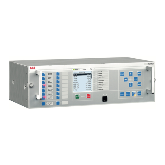
ABB RELION REF615R Manuals
Manuals and User Guides for ABB RELION REF615R. We have
5
ABB RELION REF615R manuals available for free PDF download: Technical Manual, Engineering Manual, Manual, Installation Manual
ABB RELION REF615R Technical Manual (664 pages)
Brand:
ABB
| Category:
Relays
| Size: 19.48 MB
Table of Contents
Table of Contents
7
Section 1 Introduction
29
This Manual
29
Intended Audience
29
Product Documentation
30
Product Documentation Set
30
Document Revision History
30
Related Documentation
31
Symbols and Conventions
31
Symbols
31
Document Conventions
31
Functions, Codes and Symbols
32
Section 2 REF615R Overview
37
Overview
37
Product Version History
37
PCM600 and IED Connectivity Package Version
38
Local HMI
38
Display
38
Leds
39
Keypad
40
Programmable Push Buttons with Leds
41
Web HMI
42
Authorization
43
Communication
43
Section 3 Basic Functions
47
General Parameters
47
Self-Supervision
57
Internal Faults
57
Warnings
60
Programmable Leds
61
Identification
61
Function Block
62
Functionality
62
Signals
65
Settings
66
Monitored Data
68
LED Indication Control
69
Function Block
69
Functionality
69
Time Synchronization
70
Functionality
70
Parameter Setting Groups
71
Function Block
71
Functionality
71
Fault Records FLTMSTA
73
Functionality
73
Settings
74
Monitored Data
75
Nonvolatile Memory
80
Binary Input
81
Binary Input Filter Time
81
Binary Input Inversion
82
Oscillation Suppression
82
Binary Outputs
82
Trip Output Contacts
83
Trip Outputs to
83
Dual Single-Pole High-Speed Trip Outputs HSTO1, HSTO2 and HSTO3
84
Internal Fault Signal Output IRF
85
GOOSE Function Blocks
86
GOOSERCV_BIN Function Block
86
Function Block
86
Functionality
86
Signals
86
GOOSERCV_DP Function Block
87
Function Block
87
Functionality
87
Signals
87
GOOSERCV_MV Function Block
87
Signals
88
GOOSERCV_INT8 Function Block
88
Function Block
88
Functionality
88
GOOSERCV_INTL Function Block
89
Function Block
89
Functionality
89
Signals
89
GOOSERCV_CMV Function Block
90
Function Block
90
Functionality
90
Signals
90
GOOSERCV_ENUM Function Block
90
Functionality
91
Signals
91
GOOSERCV_INT32 Function Block
91
Function Block
91
Type Conversion Function Blocks
92
QTY_GOOD Function Block
92
Functionality
92
Signals
92
QTY_BAD Function Block
92
Signals
93
T_HEALTH Function Block
93
Functionality
93
T_F32_INT8 Function Block
94
Functionality
94
Function Block
94
Settings
94
Configurable Logic Blocks
94
Shift Register SHFT
94
Identification
94
Function Block
95
Functionality
95
Operation Principle
95
Application
99
Signals
100
Settings
100
Monitored Data
101
Standard Configurable Logic Blocks
102
OR Function Block
102
AND Function Block
102
XOR Function Block
103
NOT Function Block
103
MAX3 Function Block
104
MIN3 Function Block
104
R_TRIG Function Block
105
F_TRIG Function Block
105
T_POS_XX Function Blocks
106
Local/Remote Control Function Block CONTROL
107
Function Block
107
Functionality
107
Signals
108
Settings
108
Monitored Data
109
Factory Settings Restoration
110
Load Profile Record Loadprof
110
Functionality
110
Quantities
110
Length of Record
111
Uploading of Record
112
Clearing of Record
113
Configuration
113
Signals
114
Settings
115
Monitored Data
117
Section 4 Protection Functions
119
Current Protection
119
Three-Phase Non-Directional Overcurrent Protection 51P/50P
119
Identification
119
Function Block
119
Functionality
119
Operation Principle
120
Measurement Modes
123
Timer Characteristics
123
Application
125
Signals
131
Settings
132
Monitored Data
135
Technical Data
136
Three-Phase Non-Directional Long-Time Overcurrent Protection 51LT
137
Identification
137
Function Block
137
Functionality
137
Operation Principle
137
Timer Characteristics
139
Application
140
Signals
140
Settings
141
Monitored Data
142
Three-Phase Directional Overcurrent Protection 67/51P and 67/50P137
143
Identification
143
Function Block
143
Functionality
143
Operation Principle
143
Measurement Modes
149
Directional Overcurrent Characteristics
149
Application
157
Signals
160
Settings
161
Monitored Data
165
Technical Data
166
Non-Directional Neutral Overcurrent Protection 51N/50N and Non-Directional Ground Fault Protection 51G/50G
167
Identification
167
Function Block
167
Functionality
167
Operation Principle
168
Measurement Modes
170
Timer Characteristics
170
Application
172
Signals
172
Settings
173
Monitored Data
176
Technical Data
177
Directional Earth-Fault Protection 67/51N and 67/50N
177
Advertisement
ABB RELION REF615R Engineering Manual (124 pages)
Brand:
ABB
| Category:
Relays
| Size: 18.11 MB
Table of Contents
Table of Contents
9
Section 1 Introduction
13
This Manual
13
Intended Audience
13
Product Documentation
13
Product Documentation Set
13
Document Revision History
14
Related Documentation
14
Symbols and Conventions
15
Symbols
15
Document Conventions
15
Functions, Codes and Symbols
16
Section 2 IED Engineering Process
21
Monitoring and Control System Structure
24
Standard Configuration Concept
25
Workflow
27
Section 3 PCM600 Tool
31
Connectivity Packages
32
PCM600 and IED Connectivity Package Version
33
PCM600 Projects
33
Communication between PCM600 and the IED
34
Section 4 Setting up a Project
35
Installing Connectivity Packages
35
Installing Connectivity Packages by Using the Connectivity Package Installer
35
Installing Connectivity Packages by Using the Update Manager
35
Activating Connectivity Packages
36
Setting up IP Addresses
37
Creating a New Project
38
Building the Plant Structure
39
Inserting an IED
40
Inserting an IED in Online Mode
41
Inserting an IED in Offline Mode
48
Inserting an IED from the Template Directory
49
Inserting an IED by Importing a .Pcmi File
51
Setting the IED IP Address in a Project
52
Technical Key
54
IEC 61850 Naming Conventions to Identify an IED
55
Setting the Technical Key
57
COM600 Project
60
Importing an IED in a COM600 Project
60
Using the Web HMI
64
IED User Management
65
Section 5 Protection and Control Engineering
69
Application Configuration Tool
69
Function Blocks
70
Signals and Signal Management
71
Function Block Execution Parameters
72
Execution Order and Feedback Loops
73
Configuration Parameters
74
Connections and Variables
74
Hardware Channels
75
Validation
76
Validation When Creating an Application Configuration
76
Validation on Demand
77
Validation When Writing to the IED
78
Parameter Setting Tool
78
Configuration Parameter
79
Setting Parameter
79
Setting Group
79
IED Parameter Import and Export
79
IED Parameter Organization
80
Signal Matrix Tool
80
Load Profile Tool
83
Opening and Closing Load Profile Tool
83
Load Profile Tool User Interface
86
Information Fields
87
Fault Record Tool
87
Opening and Closing Fault Record Tool
87
Fault Record Tool Interface
89
Section 6 LHMI Engineering
91
Single-Line Diagram Engineering
91
Diagrams in Graphical Display Editor
91
Display Window and Sequence Order
92
Symbol Library
93
Supported Single-Line Diagram Symbols
93
HMI Display Raster Layout and Text Font Selection
95
Text Handling
95
Adding Static Text
96
Adding Select Buttons
96
Adding a Measurand
97
Adding a Busbar
98
Adding Symbols into a Display Page
99
Drawing Lines to Create Links
100
Bay Configuration Engineering
101
Creating a Complete HMI Display Page
102
Linking Process Objects
103
Section 7 IEC 61850 Communication Engineering
107
IEC 61850 Protocol References and Pre-Conditions
107
IEC 61850 Interface
107
IEC 61850 Interface in the IED
108
GOOSE Data Exchange
108
Function View for IEC 61850 in PCM600
109
Station Configuration Description File Types
110
IEC 61850 Engineering Process
110
Exporting SCL Files from PCM600
111
Exporting SCD Files
111
Exporting ICD or CID Files
112
Engineering Vertical and Horizontal Communication
113
Importing SCL Files to PCM600
115
Importing SCD Files
115
Importing ICD or CID Files
118
Writing Communication Configuration to the IED
118
Section 8 Glossary
121
ABB RELION REF615R Manual (66 pages)
Modbus Point List Mitigation
Brand:
ABB
| Category:
Network Hardware
| Size: 1.61 MB
Table of Contents
Table of Contents
7
Introduction
13
This Manual
13
Intended Audience
13
Document Revision History
13
Related Documentation
13
Symbols and Conventions
14
Safety Indication Symbols
14
Modbus Point List Mapping Mitigations
15
Overview
15
Modbus Point List Mapping Mitigations
16
0X Registers
17
Function Code 1 (Read Coil Status)
17
Logical Output Block (Single-Bit Data)
17
Table 1. Mitigations of Modbus Registers Mapping for the Logical Output Points in Single-Bit Block
17
0X Registers
18
Physical Output Block (Single-Bit Data)
24
Table 2. Mitigations of Modbus Registers Mapping for the Physical Output Points in Single-Bit Block
24
Logical Output Block (Double-Bit Data with Momentary Change Detection)
25
Physical Output Block (Double-Bit Data with Momentary Change Detection)
25
Table 3. Mitigations of Modbus Registers Mapping for the Logical Output Points in Double-Bit Block
25
Table 4. Mitigations of Modbus Registers Mapping for the Physical Output Points in Double-Bit Block
26
1X Registers
27
Function Code 2 (Read Input Status)
27
Logical Input Block (Single-Bit Data)
27
Table 5. Mitigations of Modbus Registers Mapping for the Logical Input Block in Single-Bit Block
27
Physical Input Block (Single-Bit Data)
30
Table 6. Mitigations of Modbus Registers Mapping for the Physical Input Block in Single-Bit Block
30
1X Registers
30
Logical Input Block (Double-Bit Data with Momentary Change Detection)
31
Table 7. Mitigations of Modbus Registers Mapping for the Logical Input Block in Double Bit Block
31
Physical Input Block (Double-Bit Data with Momentary Change Detection)
32
Table 8. Mitigations of Modbus Registers Mapping for the Physical Input Block in Double-Bit Block
32
4X Registers
33
Function Code 3 (Read Holding Register)
33
User Programmable Register Block (UDR)
33
Example of Remapping a Discrete Signal to a UDR
33
Figure 1. Snapshot of CMT in UDR View
33
Table 9. Mitigations of Modbus User Defined Registers (UDR)
33
Example of Remapping an Analog Register to UDR
34
Figure 2. Snapshot of 51P Remapped to 40001:00
34
Table 10. Example and Explanation of One Digital Signal (51P) in
34
Figure 3. UDR Multiplicative Scaling Factor for "Ld0.Cmmxu1.A.phsa.instcval.mag.f
35
System Status/Configuration Block
36
Table 11. Mitigations of Modbus System Status/Configuration Block
36
Figure 4. UDR Divisor Scaling Factor to Convert a Voltage Reading from Pu to Primary KV
36
RMS Load Current/Angular Values Block
39
Table 12. Mitigations of Modbus Mappings for RMS Load Current/Angular Values Block
39
Figure 5. Snapshot on Scaling Load Current a from CMT to Read Primary Current in Ampere
39
4X Registers
40
RMS Demand Current/Real and Reactive Power Values Block
42
Table 13. Mitigation of Modbus Mappings for RMS Demand Current/Real and Reactive Power Values Block
42
RMS Peak Demand Current/Real, Reactive Power Values and Time Stamps Block
43
Table 14. Mitigation of Modbus Mappings for Peak Demand Current/Real, Reactive Power Values and Time Stamps Blocks
43
RMS Minimum Demand Current/Real, Reactive Power Values and Time Stamps
44
Table 15. Mitigation of Modbus Mappings for Minimum Demand Current/Real, Reactive Power Values and Time Stamps Block
45
Counters Block
46
Table 16. Mitigation of Modbus Mappings for Counter Block
46
Physical and Logical Input / Output State Block
47
Table 17. Mitigation of Modbus Physical and Logical Input/Output State Block
47
Function Code 16 (Preset Multiple Register)
48
Control Command Addresses Change
48
Control Command Format Change
48
Control Mask Block (Read and Write)
48
Table 18. Uniformed Control Command Format in REF615R
48
Table 19. Mitigation of Modbus Mapping for Control Mask Block
48
Function Code 23 (Read/Write 4X Registers)
51
Fault Record
51
Table 20. Mitigation of Modbus Mapping for Fault Records Block
52
Operation Records
53
Table 21. Mitigation of Modbus Mapping for Operation Records
54
Table 22. One Example of Modbus Event Record Value
54
Figure 6. Snapshot of Using CMT to Enable Modbus Event on Coil
55
6X Registers
57
Selected PCM ACT Logic Examples or Explanations
59
Logical Output Points
59
Three Phase under Voltage Trip (27-3P)
59
Instantaneous 3 Phase Over-Current Alarm Disabled (50-3D)
60
Logical Input ACT Logic Selected Examples
60
Enable Phase over Current Protection for All Phase Elements Except 50P3 (PH3)
60
Enable Ground over Current Protection for All Ground Elements Except 50N-3(GRD)
60
Figure 7. Example of Create Seal in Point for 46-1 Trip
60
Enable 50P-1 and 50N-1 (50-1)
61
Enable 50P-2 and 50N-2 (50-2)
61
Enable 50P-3 and 50N-3 (50-3)
61
Enable Alternate 1 Settings (ALT1)
61
Enable Alternate 2 Settings (ALT2)
61
The Seal in Points (Latch) Using SRGAPC Give on Example
60
1 St Instantaneous Over-Current Distance Alarm (50-1D)
59
2 Nd Instantaneous Over-Current Distance Alarm (50-2D)
59
Ground Over-Current Disabled Alarm (GRD-D)
59
Phase Over-Current Disabled Alarm (PH3-D)
59
Glossary
63
Advertisement
ABB RELION REF615R Installation Manual (48 pages)
PROTECTION AND CONTROL
Brand:
ABB
| Category:
Relays
| Size: 4.44 MB
Table of Contents
Table of Contents
9
Section 1 Introduction
11
This Manual
11
Intended Audience
11
Product Documentation
12
Product Documentation Set
12
Document Revision History
12
Related Documentation
12
Symbols and Conventions
13
Symbols
13
Document Conventions
13
Section 2 Environmental Aspects
15
Sustainable Development
15
Disposal of a Protection Relay
15
Section 3 Unpacking, Inspecting and Storing
17
Removing Transport Packaging
17
Inspecting Product and Delivery Items
17
Identifying Product
17
Checking Delivery Items
17
Inspecting Product
17
Returning a Product Damaged in Transit
18
Storing
18
Section 4 Mounting
19
Checking Environmental Conditions and Mounting Space
19
Detaching and Installing the Plug-In Unit
19
Detaching the Plug-In Unit
19
Installing the Plug-In Unit
21
Mounting the IED
22
Required Tools
22
Rack Mounting the IED
22
Flush Mounting or Semi-Flush Mounting the IED
24
Mounting Lens Sensors for an Arc Flash Detector System
28
Section 5 Connecting
31
Required Tools
31
Connecting Wires
31
Connecting Protective Grounding
31
Connecting Analog Signals
32
Connecting Current and Voltage Inputs
32
Connecting IED with a Test Switch
33
Connecting Binary Signals
33
Connecting Power Supply
33
Connecting Communication
34
Energizing the IED
34
Inner Assembly of the IED
35
Section 6 Removing, Repairing and Exchanging
37
Product Lifecycle
37
Checking Protection Relay Information
37
Removing the IED
38
Sending Protection Relay for Repair
38
Exchanging Protection Relay
38
Section 7 Technical Data
39
Case and HMI Display Variants
39
Front Side of the IED
39
Rear Side of the IED
40
Dimensions
41
Enclosure Class
42
Section 8 Accessories and Ordering Data
43
Section 9 Glossary
45
ABB RELION REF615R Manual (40 pages)
DNP3 Communication Protocol
Brand:
ABB
| Category:
Relays
| Size: 4.1 MB
Table of Contents
Table of Contents
7
Section 1 Introduction
9
This Manual
9
Intended Audience
9
Product Documentation
10
Product Documentation Set
10
Document Revision History
10
Related Documentation
10
Symbols and Conventions
11
Symbols
11
Document Conventions
11
Section 2 DNP3 Overview
13
DNP3 Standard
13
Physical Layer
13
Data Link Layer
13
Transport Pseudo-Layer
14
Application Layer Parameters
15
Communication Modes
15
Section 3 Vendor-Specific Implementation
17
DNP3 Link Modes
17
DNP3 Data Objects
17
DNP3 Serial Link Mode
17
DNP3 TCP/IP Mode
18
DNP3 Point Settings
18
Binary Input Points
18
Binary Output Status Points and Control Relay Output Blocks
18
CROB Index (Point) Types
19
Control Modes
20
Binary Output Status Points
22
Analog Inputs
23
Analog Data Scaling
24
Fault Record Time Stamp
25
DNP3 Points
26
Point Configuration
26
Class Assignment
26
Section 4 DNP3 Parameters
29
Parameter Descriptions
29
Parameter List
32
Section 5 Tolerances
35
DNP3 Timing Considerations
35
Section 6 Glossary
37
Advertisement
Related Products
ABB REF615 E
ABB REF615 F
ABB REF615 J
ABB REF615 L
ABB REF615 M
ABB REF615 A
ABB REF615 B
ABB REF615 K
ABB REF615 G
ABB REF 610
ABB Categories
Industrial Equipment
Controller
Measuring Instruments
Battery Charger
DC Drives
More ABB Manuals
Login
Sign In
OR
Sign in with Facebook
Sign in with Google
Upload manual
Upload from disk
Upload from URL