Table of Contents
Advertisement
Quick Links
Download this manual
See also:
Maintenance Manual
Advertisement
Table of Contents

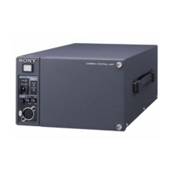
Summary of Contents for Sony CCU-590
- Page 1 CAMERA CONTROL UNIT CCU-590/590P OPERATION MANUAL [English] 1st Edition (Revised 1)
- Page 2 Rear : 10 cm (4 inches) or more WARNING For the customers in the U.S.A. (for CCU-590) To reduce the risk of fire or electric shock, This equipment has been tested and found to comply with the do not expose this apparatus to rain or limits for a Class A digital device, pursuant to Part 15 of the FCC Rules.
-
Page 3: Table Of Contents
Rear panel ................. 6 Internal Switches and Internal Boards ....... 9 Internal switches ................9 Internal boards ................9 Connecting the CCU-590/590P to the Video Camera ..10 Notes on connections .............. 10 Self-Diagnostics ..............11 Settings of the camera.............. 11 Status display of the camera system ........11 Self-diagnostics of the camera system........ -
Page 4: Overview
75 to 750 m (with BELDEN 9232 φ13.2 mm cables), or 100 to 1,000 m (with Fujikura φ14.5 mm cables). Rack mountable Two CCU-590/590Ps can be mounted side by side in a standard 19-inch EIA rack when using an optional RMM- 301 Rack Mount Adaptor. Overview... -
Page 5: Function And Location Of Parts And Controls
CCU- Note 590/590P goes on air). When the CALL button on the If the fan in the CCU-590/590P stops, the MAIN indicator video camera, MSU-900/950, RCP-750/751/920/921 will flash to warn you of the abnormal condition. If this... -
Page 6: Rear Panel
CCU-590/590P. of the internal AU board. ENG: Engineer line. The settings regarding the output intercom signals can be performed on the internal AU board. For details, consult your Sony service personnel. Rear panel a CAMERA connector b AUDIO OUTPUT connectors... - Page 7 B RET-1 connectors To use this connector, it is required to change the setting of the internal board. For details, consult your Sony service C RET-2/PROMPTER connectors personnel. F SPARE connector (BNC type) D SDI RET-3/RET-4 connectors Not used.
- Page 8 Connects to an AC power source using the supplied AC D SYNC connector power cord. Secure the power cord to the CCU-590/590P Connect to the synchronous signal input connector on a using the supplied plug holder.
-
Page 9: Internal Switches And Internal Boards
The following switches are located inside the unit, behind the front panel. b Headset microphone switch 2 (S6) a Headset microphone switch 1 (S5) For details on the internal boards, consult your Sony service personnel. c Internal main power switch a Headset microphone switch 1 (S5) -
Page 10: Connecting The Ccu-590/590P To The Video Camera
CA-905K/F/T Notes • The maximum power output from the CAMERA connector of the CCU-590/590P is 110 watts (including a cable loss of 10 watts). Do not connect any equipment which consumes more To an AC power source than 110 watts of power. -
Page 11: Self-Diagnostics
Self-Diagnostics The CCU-590/590P is equipped with the self-diagnostic function and you can display the self-diagnostics results of the system and the internal boards of the CCU-590/590P on the following monitors. • A picture monitor connected to the PIX connector • An SDI monitor connected to the VBS/SDI-3 connector •... -
Page 12: Settings Of The Network
The following pages appear only when the CCU-590/590P Page 2 is set so that it connects to the system through the Ethernet. In order for the CCU-590/590P to establish connection via Ethernet, internal settings must be made. For details on the internal settings, consult your Sony service personnel. -
Page 13: Self-Diagnostics Results Of The Ccu-590/590P Internal Boards
Page 2 DM board CAM Video: Status of the Y, R-Y, and B-Y signals of the NS Mode: Setting for the ETHERNET connection mode triax signal LEGACY: Connection mode for the REMOTE Skin Gate: Reception status of the Skin gate signal from connector (factory-setting) the camera BRIDGE: ETHERNET connection mode... -
Page 14: Self-Diagnostics Results Of The Camera Internal Boards
Gen Lock: Locking status BoardID: ID number of the IV board CCU Power: CCU power supply type (AC/DC) and power EN board supply status BATT Volt: Voltage of the coin battery supplied with the AT board PLL Volt: Status of the PLL circuit of the AT board CCU Mode: Operation mode of the CCU PLD: Status of the PLD mounted on the AT board and program version of the PLD... -
Page 15: Rom Version Indication
ROM version indication Specifications General Power consumption 100 - 240 V AC, 50/60 Hz, maximum 1.8 A Peak inrush current (1) Power ON, current probe method: 50 A (240 V) (2) Hot switching inrush current, measured in accordance with European standard EN55103-1: 10 A (230 V) Exiting the Self-diagnostic mode 50 to 700 m (Fujikura φ8.5 mm) -
Page 16: Camera Input/Output Signals
1.0 Vp-p, 75 ohms Always verify that the unit is operating properly before BNC type (1) use. SONY WILL NOT BE LIABLE FOR DAMAGES NTSC: 714 mVp-p, 75 ohms OF ANY KIND INCLUDING, BUT NOT LIMITED PAL: 700 mVp-p, 75 ohms TO, COMPENSATION OR REIMBURSEMENT ON Encoded output: 1.0 Vp-p, 75 ohms... - Page 17 The material contained in this manual consists of information Trademark that is the property of Sony Corporation and is intended solely Ethernet is a registered trademark of Xerox Corporation. for use by the purchasers of the equipment described in this manual.
- Page 18 CCU-590/590P Sony Corporation (UC/CE) 3-869-638-02 (1) © 2007...


