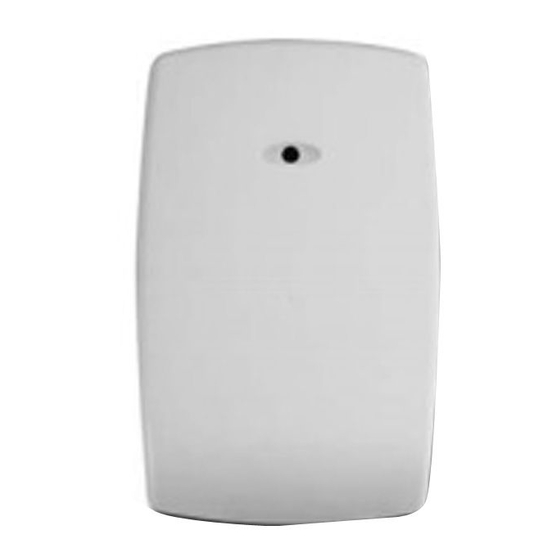
Honeywell FlexGuard FG-1625SN V-Plex Installation Instructions
Glassbreak detector
Hide thumbs
Also See for FlexGuard FG-1625SN V-Plex:
- Product manual (23 pages) ,
- Brochure & specs (41 pages)
Advertisement
Quick Links
®
FlexGuard
FG-1625SN V-Plex Glassbreak Detector Installation Instructions
Refer to Supplemental Information (next page) for complete descriptions of these installation steps
FG1625SN V-Plex Glassbreak Detector
Mounting Hole
Microphone
Bar Code
(serial no.)
DIP Switch
Mounting Hole
Front Cover
Cover Screw Location
Select Mounting Location
Wall Mount
(Top View)
Ceiling Mount: (Side View)
Test Location w/ 9V Battery
9V
Set Sensitivity Configuration
SENS1 & SENS2 configure sensitivity
SENSITIVITY
APPROXIMATE
SENS1
RANGE
MAX
25 ft (7.6m)
MEDIUM
15 ft (4.6m)
LOW
10 ft (3m)
LOWEST
5 ft (1.5m)
Note: Ranges are approximate and vary with each
room's acoustic properties. Always verify range with a
FG-701 Glassbreak Simulator.
5-051-739-00B
Enable Wall Tamper
• Remove plastic tab from rear of detector.
• Install wall tamper screw as shown.
Tamper Switch
• Set screw depth to make contact w/ bottom of
Rear Tamper
tamper cavity when device is installed
Wire Entry Hole
Terminal Block
Test Mode Pads
LED Indicators
Max. screw head size
1625SN_001-V0
Connect Detector
Connect detector to the polling loop using 18 to 22 AWG
wire, with ends stripped approximately 6mm (1/4 inch).
Be sure to observe proper polarity!
1625_ceiling_mnt-001-V0
FG1625SN V-Plex (Polling Loop) Wiring
Prepare Housing for Surface Wiring (Optional)
The back of the housing has four wire channels to
accommodate surface wiring. If surface wiring is to be
used, select the appropriate wire channel and remove
the breakout tab by inserting a flathead screwdriver
under the tab and prying upward.
1625SN_009-V0
SENS1
Wire Channel
Breakout Tabs
SENS2
Mount Detector
• Place unit over wall tamper screw, if used.
• Use mounting holes as template to mark ceiling or
wall.
• Mount detector using appropriate hardware.
SENS2
NOTE: A screw retention feature designed to
make ceiling mounting easier will cause some
OFF
OFF
resistance when inserting the screw into the plastic.
ON
OFF
OFF
ON
ON
ON
Wire Channel
Breakout Tabs
9.7 mm (.38")
4.2 mm or 4.8 mm
(#8 or #10)
Wire Channel
Breakout Tabs
1625Wiring_004-V0
Wire Channel
Breakout Tabs
Wire Channel
Breakout Tabs
1625SN_WireChan-V0
Page 1
*
3.5 mm or 4.2 mm
(#6 or #8)
*
3.5 mm (#6) screws
work best with the screw
retention feature.
Test Detector Installation
Enter Test Mode using FG-701 (see Testing the
Detector on the next page) or manually by shorting
Test Mode pads (as below). Test Mode will
automatically time out after five minutes.
IMPORTANT NOTE: Close Cover while testing.
Install Cover Screw (optional)
2.9 mm (#4) screw,
6 mm (1/4") long
1625_008-V1
TEST
Advertisement

Summary of Contents for Honeywell FlexGuard FG-1625SN V-Plex
- Page 1 ® FlexGuard FG-1625SN V-Plex Glassbreak Detector Installation Instructions Refer to Supplemental Information (next page) for complete descriptions of these installation steps FG1625SN V-Plex Glassbreak Detector Enable Wall Tamper • Remove plastic tab from rear of detector. • Install wall tamper screw as shown. Tamper Switch Mounting Hole •...
- Page 2 Alarm LED lights for five seconds. undesired operation. openings. If required by the location, install wall The user is cautioned that changes or modifications not expressly approved by Honeywell Testing the Detector (audio signals only): could void the user’s authority to operate this equipment.


