Table of Contents
Advertisement
Quick Links
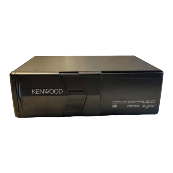
CD AUTO CHANGER
KDC-C715/Y
SERVICE MANUAL
When transporting this model, always attach CAUTION
CARD and STEPPED SCREW (for transportation).
CAUTION CARD
STEPPED SCREW : N09-4186-25
Dressing Panel
(A21-3536-12)
Bracket (L)
(J19-4710-13)
Bracket (R)
(J19-4711-13)
Blind Plate
(F19-1303-04)
Screw Set
K/E Type:
(N99-1645-15)
M Type:
(N99-1628-15)
The MECHANISM OPERATION DESCRIPTION is the same as model KDC-C710.
Please refer to the service manual of model KDC-C710 (B51-7104-00).
: B58-1275-04
Dressing Panel
(A21-3539-12)
Holder Assy (Magazine)
(J19-4676-52)
Mounting Hardware Assy
(J21-7775-04)
M Type Only
KDC-C715/Y
© 1999-12 PRINTED IN JAPAN
B51-7553-00 ( N ) 3444
Service jig
For initial position setting
Panel
(A64-1992-01)
COMPACT DISC AUTO CHANGER
NEW ANTI VIBRATION MECHANISM
COMPACT
TEXT
DIGITAL AUDIO
Adhessive Tape
(J69-0506-04)
Parts No.
W05-0635-00
KDC-C715
DISC NAME PRESET
10
DISC
Cord With Plug
(E30-4138-05)
Advertisement
Table of Contents

Summary of Contents for Kenwood KDC-C715/Y
- Page 1 KDC-C715/Y CD AUTO CHANGER KDC-C715/Y SERVICE MANUAL © 1999-12 PRINTED IN JAPAN B51-7553-00 ( N ) 3444 Service jig Parts No. When transporting this model, always attach CAUTION For initial position setting W05-0635-00 CARD and STEPPED SCREW (for transportation). CAUTION CARD...
- Page 2 KDC-C715/Y BLOCK DIAGRAM...
-
Page 3: Microcomputer's Terminal Description
KDC-C715/Y MICROCOMPUTER’S TERMINAL DESCRIPTION UPD784214GC (X32-4660-00, IC7) Pin No Name Processing, Operation TOUT Test output TSTB Text data strobe signal H: Focusing OK. L:Focusing NG. X OFF H: Servo IC oscillation OFF. L: Servo IC reset. H: Parameter setting. L: Address register setting. - Page 4 KDC-C715/Y MICROCOMPUTER’S TERMINAL DESCRIPTION Pin No Name Processing, Operation DATAC Data output to H/U. HCLK H:Clock input. L:Clock output. REQC Communication request to H/U. CHMUTE L:Muting ON. Text data output. Text data input. TSCK Text clock output. 48Å`55 A0Å`7 S-RAM address setting.
- Page 5 KDC-C715/Y ADJUSTMENT LPS initial position adjustment procedure Connect the changer to the H/U. While holding the maga- zine eject button of the changer, press the reset button of the H/U and, in about 1 second, release the magazine eject button. Press the CD button of the H/U to enter the E-88 mode.
-
Page 6: Pc Board (Component Side View)
PC BOARD (COMPONENT SIDE VIEW) X13-9730-00/9740-00 (J74-0987-01) X13-9000-00 (J74-0619-12) A-GND BU14V CH-CON REQH DATAC CH-RST DATAH REQC CH-MUTE CH-CLK MGND LOESW 8/12SW (FOIL SIDE VIEW) X13-9730-00/9740-00 (J74-0987-01) X13-9000-00 (J74-0619-12) GND A-GND BU14V CH-CON REQH DATAC CH-RST DATAH REQC CH-CLK CH-MUTE MGND LOESW 8/12SW... - Page 7 PC BOARD (COMPONENT SIDE VIEW) (FOIL SIDE VIEW) X32-4660-00/4670-00 (J74-0966-01) X32-4660-00/4670-00 (J74-0966-01) C180 R180 R180 C180 TROFF TROFF C190 C190 R191 R191 C194 C194 SGND C193 C193 SGND R161 R161 PUGND PUGND LIMSW LIMSW SA5V SA5V LOESW LOESW FCLK FCLK R121 R121 CH MUTE...
- Page 8 (X32-4660-0X) MGSW AVREF0 COMMSW R129 RESET RESET IC CHRST EJSW 5.0V (X13-9000-00) ARMSW OUT 1 5.0V REQH RESET CH CON CHCON BU+14V BU+14V BU14V CH-CON BU+14V CH-RST CH MUTE CH-RST A GND Q6,7 R-CH R-ch A. MUTE FCLOCK CH RST A-GND 12.5MHz LPSCO...
- Page 9 B LINE 2.5V ELV- 9.1K C184 R184 ELVD+ ELVD- 120K 3.2V 3.5V 2.0V 2.0V 5.0V 5.0V 3.2V 3.2V 2.8V 2.5V 2.5V 2.5V 2.5V 4.2V MOTOR DRIVER 2.5V C192 0.33 2.5V R193 C194 820P R191 TROFF 120K SP/LOD- SP/LOD+ SERVO KDC-C715/Y...
- Page 10 KDC-C715/Y EXPLODED VIEW (MECHANISM) M2x3.5 N09-4126-05 M2x2.5 (BLK) N39-2025-45 M2x5 N86-2005-46 M1.7x1.5 (BLK) N09-4189-05 N09-4154-05 Ø M1.7x3 N09-4181-05 M1.7x2.2 N39-1722-46 M2x5 N86-2005-46 2x3.5 N09-4120-15 Ø 1.6x4 WASHER N19-2058-04 Ø WASHER N19-2080-04 Ø 1.6x3.5 WASHER N19-2028-04 Ø FPC1 Parts with the exploded numbers larger than 700 are not supplied.
-
Page 11: Exploded View (Unit)
KDC-C715/Y EXPLODED VIEW (UNIT) 218R 218L BLACK N09-4186-25 N89-2004-46 Ø 2.6x6 (BLK) N89-2606-45 Ø SILVER (X13-9000-00) Parts with the exploded numbers larger than 700 are not supplied. -
Page 12: Parts List
KDC-C715/Y PARTS LIST ∗New Parts KDC-C715/Y Parts without Parts No. are not supplied. SUB-CIRCUIT UNIT (X13-9000-00) Les articles non mentionnes dans le Parts No. ne sont pas fournis. SUB-CIRCUIT UNIT ME1 (X13-9730-00) CD PLAYER UNIT (X32-4660-00) Teile ohne Parts No. werden nicht geliefert. - Page 13 KDC-C715/Y PARTS LIST ∗New Parts Parts without Parts No. are not supplied. Les articles non mentionnes dans le Parts No. ne sont pas fournis. Teile ohne Parts No. werden nicht geliefert. CD PLAYER UNIT (X32-4660-00) Dest Dest inati inati Ref. No.
- Page 14 KDC-C715/Y PARTS LIST ∗New Parts Parts without Parts No. are not supplied. Les articles non mentionnes dans le Parts No. ne sont pas fournis. CD PLAYER UNIT (X32-4660-00) MECHANISM ASSY (X92-3630-00) Teile ohne Parts No. werden nicht geliefert. Dest Dest Ref.
-
Page 15: Specifications
Installation Size (WxHxD) ..................250x80x176mm (9-13/16x3-1/8x6-13/16 in.) Weight ........................2.0kg (4.4lbs) KENWOOD follows a policy of continuous advancements in development. For this reason specifications may be changed without notice. KENWOOD CORPORATION 14-6, Dogenzaka 1-chome, Shibuya-ku, Tokyo 150-8501 Japan KENWOOD SERVICE CORPORATION KENWOOD ELECTRONICS ITALIA S.p.A.


