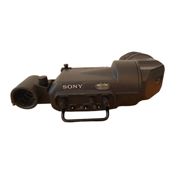
Summary of Contents for Sony BVF-20W
- Page 1 ELECTRONIC VIEWFINDER BVF-20W/20WCE [Japanese/English/German] OPERATION MANUAL 1st Edition (Revised 1) Serial No. 10001 and Higher (UCJ) Serial No. 40001 and Higher (EK)
- Page 2 For the customers in Europe WARNING WARNING To prevent fire or shock hazard, do not This is a Class A product. In a domestic environment, this expose the unit to rain or moisture. product may cause radio interference in which case the user may be required to take adequate measures.
-
Page 3: Table Of Contents
Table of Contents Outline ....................2(E) Location and Function of Parts ............3(E) Attaching the Viewfinder to a Camera ..........5(E) Adjusting the Focus and Screen ............6(E) Detaching the Eyepiece ............... 7(E) Attaching the Microphone ..............8(E) Name and Function of the Indicators ..........10(E) Cleaning the Screen or Interior ............ -
Page 4: Outline
Outline The BVF-20W/20WCE is a wide-aspect 2-inch screen Removable Eyepiece (aspect ratio 16:9) viewfinder which can be attached to a Sony BVP-550 series color video camera. Detaching the eyepiece gives you a clear view of the center of the screen even with your eye away from the The BVF-20W/20WCE has the features described viewfinder. -
Page 5: Location And Function Of Parts
Location and Function of Parts 1 Plug Viewfinder cable 2 Stopper 3 Tally indicator (rear) Microphone holder Eyecup 4 Diopter adjustment ring 5 Tally indicator (front) 6 PEAKING control 7 CONTRAST control PEAKING CONTRAST BRIGHT 8 BRIGHT control DISPLAY ZEBRA TALLY HIGH 9 TALLY switch... - Page 6 Location and Function of Parts 1 Plug !º ZEBRA (zebra pattern) switch Connect to the VF connector on the camera. Controls the zebra pattern display on the viewfinder screen as follows: 2 Stopper ON: A zebra pattern appears and stays. Prevents the viewfinder from coming off the camera OFF: The zebra pattern disappears.
-
Page 7: Attaching The Viewfinder To A Camera
Attaching the Viewfinder to a Camera Slide rail Slide guide Left-right positioning ring Stopper Plug VF connector Loosen the left-right positioning ring on the Position the viewfinder by sliding it from side to camera. side, and tighten the left-right positioning ring on the camera. -
Page 8: Adjusting The Focus And Screen
Adjusting the Focus and Screen Adjusting the focus Turn the diopter adjustment ring until the image is sharpest for your eyesight. Diopter adjustment ring Adjusting the screen To adjust the peaking, brightness and contrast of the viewfinder screen rotate the controls which are illustrated below. -
Page 9: Detaching The Eyepiece
Detaching the Eyepiece Detaching the eyepiece gives you a clear view of the For details on cleaning the viewfinder or attaching the fogproof filter, see “Cleaning the Screen and Interior” on screen even with your eye away from the viewfinder. page 11(E). -
Page 10: Attaching The Microphone
Attaching the Microphone Proceed as follows to attach the supplied microphone. Loosen the screw of the microphone holder and open the holder. Attach the microphone to the microphone holder, then close the holder and tighten the screw. Insert the microphone plug into When connecting the microphone to the camera adaptor, you will need to set the microphone selector. - Page 11 Attaching the microphone to the cradle suspension Using the optional CRS-3P Cradle Suspension and microphone holder (A) will reduce noise caused by vibration. Combine together the CRS-3P CRS-3P Cradle Suspension (not supplied) Cradle Suspension and the microphone holder (A) (Part No.
-
Page 12: Name And Function Of The Indicators
Name and Function of the Indicators The following indicators are arranged above and below Function of each indicator may vary with the camera you are using. Please refer to the manual supplied with your the viewfinder screen to show the status or settings of camera to confirm the indicators’... -
Page 13: Cleaning The Screen Or Interior
Cleaning the Screen or Interior When cleaning the screen or the interior of the Fog-proof filter viewfinder, detach the viewfinder from the camera, then clean it taking care not to damage the Depending on the temperature and humidity, the components. protecting filter may mist, especially if you breathe near it. -
Page 14: Specifications
Specifications General Accessories not supplied Power requirements BKW-401 Viewfinder Rotation Bracket 9.3 V DC Fog-proof filter (Part No. 1-547-341-11) Power consumption Lens assembly (farsighted) (–2.8 D to +2.0 D) (Part 2.3 W No. A-8262-537-A) Operating temperature Lens assembly (low magnification) (–3.6 D to –0.8 D) –20˚C to +45˚... - Page 15 The material contained in this manual consists of information that is the property of Sony Corporation and is intended solely for use by the purchasers of the equipment described in this manual. Sony Corporation expressly prohibits the duplication of any...
- Page 16 Sony Corporation BVF-20W/20WCE (UCJ/EK) 1996.07.13 Broadcast Products Company 1996 3-856-992-02 (1) Published by Broadcast Products Company...


